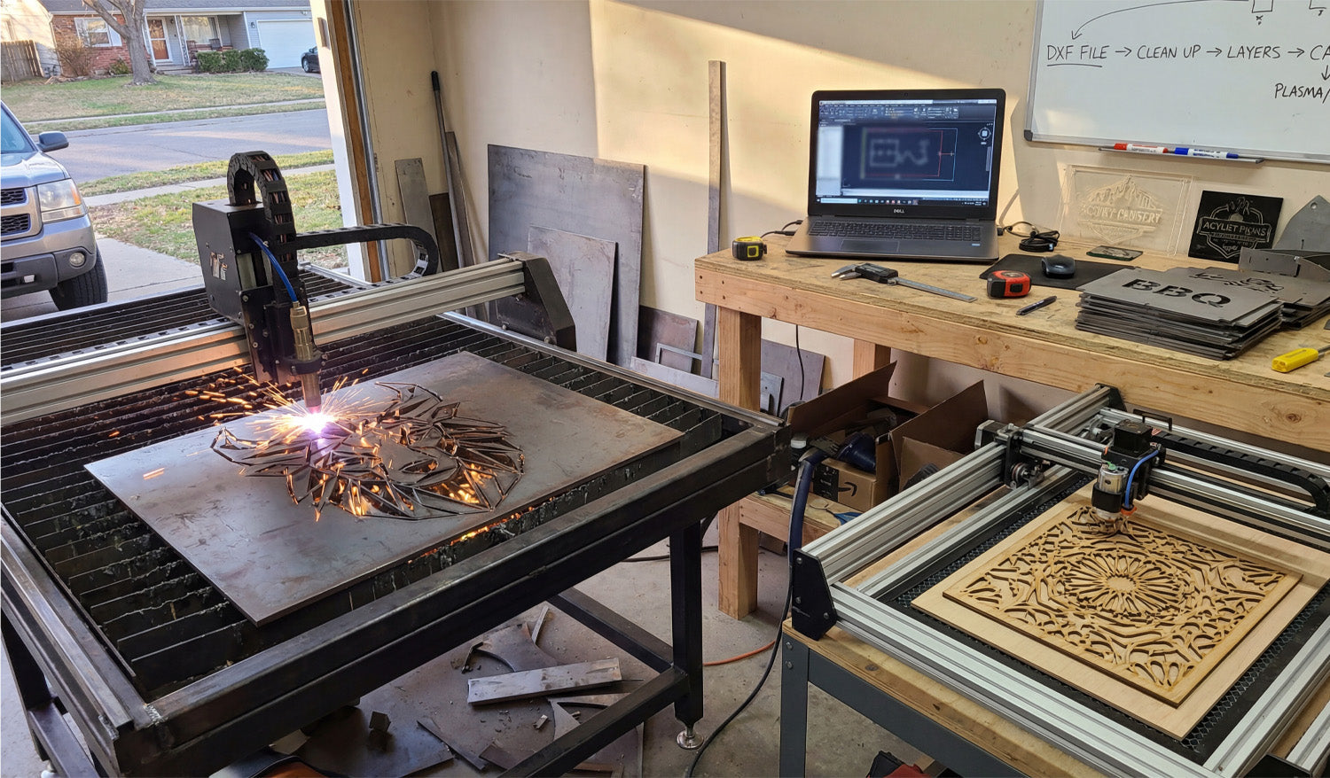
Using DXF files for laser and plasma cutting projects is all about starting with clean vector artwork, setting up the right layers and scale, and then turning those paths into safe, efficient toolpaths your machine can follow without surprises.
Why DXF Files Work So Well for Laser and Plasma Cutting
Laser and plasma cutters both love vector geometry. DXF (Drawing Exchange Format) files store shapes as exact lines, arcs, and curves instead of pixels, which makes them ideal for 2D cutting.
- Accurate shapes: Holes, slots, and contours are defined by coordinates, not by fuzzy image edges.
- Easy scaling: You can resize designs to fit different sheet sizes without losing quality.
- Wide support: Almost every CAD, CAM, and controller software understands DXF.
Whether you are cutting intricate wall art on a laser or thick steel parts on a plasma table, DXF files give you a reliable starting point.
Step 1: Plan the Project Around Your Machine and Material
Before opening any DXF file, think about the real-world setup you will use:
- Machine type: Laser for fine, clean edges; plasma for thicker, structural metal work.
- Material: Wood, acrylic, and thin metals for lasers; mild steel, stainless, or aluminum for plasma.
- Thickness: This affects minimum detail size, kerf width, and cutting speed.
Knowing these basics up front helps you choose or adjust DXF designs that will actually cut well on your specific machine.
Step 2: Choose or Create DXF Files That Fit the Process
You can either draw DXF files yourself or use ready-made designs, but in both cases, think “laser/plasma friendly.”
- For lasers: Fine detail is possible, but avoid hairline bridges that can burn away.
- For plasma: Use bold shapes, thicker webs, and avoid tiny interior cutouts that may deform or blow out.
- For both: Keep the overall design simple enough that it cuts cleanly and quickly.
Look for DXF designs that mention being tested on laser or plasma cutters, or adapt existing artwork to better match your process.
Step 3: Open the DXF and Check Scale and Units
One of the most common early mistakes is wrong scale. Always verify the size as soon as you import the DXF.
- Confirm whether the file was designed in mm or inches.
- Use a measurement tool in your CAD/CAM software to check a known dimension.
- If needed, scale once to correct size—then lock that in and avoid repeated scaling.
Getting the scale right at the beginning saves you from discovering that a “10 inch sign” actually came out 10 cm wide.
Step 4: Clean Up the Geometry for Laser and Plasma
Laser and plasma toolpaths depend on clean, connected geometry. Before generating any code, inspect and tidy your DXF.
- Close all loops: Make sure outside profiles and inside cutouts are fully closed paths.
- Remove duplicates: Delete overlapping lines and arcs that would cause double cutting.
- Eliminate tiny fragments: Get rid of random points, micro shapes, and leftover construction lines.
- Join polylines: Where possible, join segments into continuous polylines to improve motion.
Clean geometry helps the CAM software generate predictable, smooth toolpaths for both laser and plasma cutting.
Step 5: Use Layers to Separate Cutting and Engraving
Most DXF-based workflows work best when you use layers or colors to tell the machine what each line should do.
- Create layers such as OUTER_CUT, INNER_CUT, ENGRAVE, and MARKING.
- Put outside contours on OUTER_CUT and holes/slots on INNER_CUT.
- Place engraving lines and text on ENGRAVE, and layout marks or bend lines on MARKING.
- Keep dimensions and centerlines on a reference layer that will never be cut.
Later, in CAM or your controller software, you can map each layer to different power, speed, or cutting depth settings.
Step 6: Adapt Detail Level for Laser vs Plasma
Laser and plasma cutting respond differently to fine detail, even when they use the same DXF.
Using DXF Files for Laser Cutting
- Lasers can handle small text and intricate patterns, especially in thin materials.
- Still avoid ultra-thin bridges that might char, warp, or snap easily.
- Use separate layers for engraving vs cutting, so you can assign different power levels.
Using DXF Files for Plasma Cutting
- Use bolder shapes and keep narrow webs wider than your kerf plus a safety margin.
- Simplify tiny internal details that plasma cannot hold reliably at your material thickness.
- Give holes and slots enough size to cut round and clean, not tapered or distorted.
Designing once but tailoring detail for each process lets you reuse DXF files across more machines without constant redesign.
Step 7: Plan Kerf, Tabs, and Cut Order
With laser and plasma, how you use the DXF is just as important as the drawing itself.
- Kerf compensation: Use inside/outside offsets in CAM so parts come out to the right size.
- Cut order: Cut inner features first, then the outer profile last so parts do not move early.
- Tabs for small parts: Add small tabs in CAM to keep small pieces from tipping or falling through the grid.
- Pierce locations: Let CAM place pierces away from sharp corners or critical detail whenever possible.
Well-planned kerf and cut order turn a good DXF into a clean, efficient cutting job on either machine.
Step 8: Nest Multiple DXF Parts for Better Material Use
For bigger projects, you will often cut multiple parts or designs from one sheet. Nesting helps you get the most out of your material.
- Arrange DXF parts to minimize scrap while keeping enough spacing between cuts.
- Rotate parts as needed, especially for designs that are not direction-sensitive.
- For plasma, avoid extremely thin skeletons that may twist or drop as you cut.
- Save nested layouts as separate DXF or CAM files for repeat jobs.
Good nesting is one of the biggest ways to turn DXF designs into profitable laser and plasma projects.
Step 9: Test, Adjust, and Save “Proven” DXF Setups
Even with solid DXF files, your first run on a new material or machine is a test. Treat it that way.
- Cut a small section or sample panel to confirm fit, edge quality, and detail.
- Adjust speeds, power, or kerf settings based on how the test looks.
- If you change the design for better cutting, save a new revision of the DXF.
- Mark that version as your production-ready file for that material and thickness.
Over time, you build a library of DXF files and CAM settings that you can trust to run again with minimal tweaking.
Step 10: Keep Your DXF Files Organized by Process and Thickness
As you create more laser and plasma projects, staying organized keeps you efficient.
- Use separate folders for Laser and Plasma versions of your DXF files.
- Within each, group designs by material and thickness (for example, Steel_3mm, Birch_6mm, Acrylic_4mm).
- Include the process and size in the file name, such as
wolf_panel_laser_600mm_wood.dxforyard_sign_plasma_steel3mm.dxf.
This makes it easy to grab the right DXF file for a specific machine and material without guesswork.
Conclusion
Using DXF files for laser and plasma cutting projects gives you a predictable, repeatable way to turn vector designs into clean cuts in wood, metal, acrylic, and more. By checking scale, cleaning geometry, organizing layers, adapting detail to each process, and planning kerf and nesting in CAM, you can use the same DXF workflow to handle everything from small custom signs to full production runs with confidence.


