CNC & DXF Design Guides
CNC & DXF Design Guides

The Ultimate Guide to DXF Files: The Standard for CNC Cutting
If you own a CNC machine, you have likely heard the term "DXF" tossed around constantly. It is the heartbeat of modern digital manufacturing. Whether you are running a plasma cutter in a large industrial shop or a diode laser in your garage, the DXF file is the bridge between your creative idea and the physical object. In this guide, we will break down exactly what a DXF file is, why it is the industry standard for CNC, and how mastering this file format can transform your manufacturing process from frustrating to effortless. What is a DXF File? The acronym DXF stands for Drawing Exchange Format. It was originally developed by Autodesk in 1982 to allow different Computer-Aided Design (CAD) programs to share data with each other. Before DXF, sharing a design between different software was nearly impossible. DXF file format and universal compatibility Think of a DXF file as the "universal translator" of the design world. It takes the geometry of a design—lines, arcs, circles, and points—and saves it in a text-based format that almost any CNC software can read. Unlike an image file (like a JPG or PNG) which is made of pixels, a DXF file is made of mathematical vectors. This distinction is crucial for CNC machining because the machine needs to know the exact path to travel, not just what the picture looks like. How Does a DXF File Work with CNC? Process of converting DXF to G-Code At its core, a CNC machine is blind; it needs specific instructions on where to move. The DXF file provides the map for these movements. Here is the typical workflow: Design: You create or download a vector design saved as a .dxf file. Import: You load this file into your CAM (Computer-Aided Manufacturing) software (like SheetCam, LightBurn, or Fusion 360). Toolpathing: The software reads the vector lines in the DXF and converts them into coordinates. Cutting: The software generates "G-Code," which tells the motors exactly where to go to cut the material. Without a clean DXF file, the CAM software cannot generate a smooth toolpath, leading to rough cuts or machine errors. Key Characteristics of a CNC-Ready DXF Vector lines and nodes in a design Not all DXF files are created equal. Just because a file ends in ".dxf" does not mean it is ready for a CNC machine. A high-quality, cut-ready DXF file—like the ones we offer in our Full Access Bundle—must have specific characteristics: Closed Paths: Every shape must be a continuous loop. If a line is broken, the CNC machine won't know where to stop or start, often resulting in an incomplete cut. No Intersections: Lines should not cross over each other unintentionally, as this can cause the machine to cut the same area twice or ruin the piece. Optimized Nodes: A good DXF file uses the minimum number of "nodes" (points) to define a curve. Too many nodes can cause the machine to stutter, resulting in a jagged edge. Single Layers: Ideally, the cut lines should be on a single layer to avoid confusion during the import process. Advantages of Using DXF Files Benefits of using vector files for manufacturing DXF files offer massive advantages over other formats when it comes to CNC machining. Here are the key benefits: Infinite Scalability: Since DXF files are vectors, you can resize a design from a small keychain to a massive driveway gate without losing any quality or resolution. Universal Compatibility: Whether you use AutoCAD, CorelDRAW, Adobe Illustrator, or Inkscape, you can open and edit DXF files. Precision: DXF files hold mathematical accuracy. If you draw a line that is 100mm long in the file, the machine will cut exactly 100mm. Editability: Unlike an image, you can easily modify a DXF file. You can delete parts, add text, or combine different designs to create something new. Applications of DXF Files in Industry Examples of products made with DXF files The versatility of the DXF format makes it the go-to standard for countless industries. Here is where they are most commonly used: Metal Art & Decor: Creating intricate wall art, privacy screens, and fire pits using Plasma or Laser cutters. Automotive & Engineering: Cutting brackets, gaskets, and mechanical parts with high precision. Sign Making: Producing channel letters and logos for businesses using CNC routers or lasers. Woodworking: Designing flat-pack furniture, inlays, and engravings. Textile & Leather: Cutting patterns for clothing and upholstery using automated knife cutters. DXF Resources for Hobbyists and Professionals While learning to draw your own DXF files from scratch is a valuable skill, it is also time-consuming. For many businesses and hobbyists, the most efficient workflow is to start with a high-quality template. At DXF Files for CNC, we specialize in providing "cut-ready" designs that have been tested to ensure they work perfectly. Whether you are looking for Free DXF Files to test your machine or a premium collection to start selling products, having a reliable library of designs is essential for success. Bottom Line The DXF file is the universal language of the CNC world. It enables the precision, repeatability, and creativity that modern manufacturing demands. By understanding how these files work and ensuring you are using high-quality, optimized vectors, you can maximize the potential of your machine and produce professional-grade work every time. Whether you are a seasoned fabricator or just bought your first CNC table, the quality of your output starts with the quality of your file. Master the DXF format, and you master your machine.

The Evolution of Design: How DXF Files Power Modern CNC Machining
Computer Numerical Control (CNC) technology has revolutionized the way we build, create, and manufacture products. At the heart of this revolution lies a silent hero: the DXF file. Just as a musician needs sheet music to play a symphony, a CNC machine needs a precise digital design to create a masterpiece. in this article, we will explore the evolution of digital design files, how they bridge the gap between imagination and reality, and why high-quality vectors are crucial for your business success. The Origins of Digital Manufacturing The roots of modern CNC cutting can be traced back to the evolution of Computer-Aided Design (CAD). Before we had the sophisticated .dxf (Drawing Exchange Format) files we use today at DXF Files for CNC, manufacturing relied heavily on manual drafting and blueprints. Engineers and artists had to calculate every curve and angle by hand, which was a slow process prone to human error. From Manual Drafting to Digital Lines The earliest days of manufacturing involved transferring drawings from paper to physical templates. This method was rigid and limited the complexity of designs. The game changed with the introduction of universal file formats in the early 1980s. The goal was simple: create a "universal language" that different software and machines could understand. This development made it possible to share designs across the globe. What started as simple geometric lines evolved into the intricate, artistic patterns we see in metal wall art, fire pits, and privacy screens today. The Current State of CNC Design Files Today’s CNC ecosystem is far more advanced. We are no longer limited to simple shapes. Now, designers can create elaborate landscapes, realistic animal portraits, and complex geometric patterns that can be cut with laser, plasma, or waterjet machines. The DXF file has become the industry standard for 2D cutting. Modern Compatibility and Standards One of the defining characteristics of modern CNC projects is interoperability. A well-designed DXF file works seamlessly whether you are using a hobbyist diode laser or an industrial high-definition plasma cutter. Accuracy is key here; the digital nodes in the file must be perfectly connected to ensure the machine produces a clean cut. Modern design software allows us to optimize these files specifically for cutting processes, reducing "pierce points" and optimizing the cut path to save time and materials. Advantages of Using High-Quality DXF Files Using professional-grade designs offers several key advantages that directly impact the profitability of a CNC business: Precision and Clean Edges: High-quality files are free from "double lines" or "open loops," ensuring your machine cuts smoothly without stopping or ruining the material. Efficiency and Speed: Optimized designs reduce cutting time. For a business, time is money. A clean file means faster production cycles. Versatility: A single DXF design can be resized for a keychain or scaled up for a massive garden gate without losing quality. Cost-Effectiveness: Purchasing a ready-to-cut design pack, like our Full Access Bundle, saves you hundreds of hours of drawing time, allowing you to focus on fabrication and sales. Customization: DXF files act as a perfect base. You can easily add a customer’s name to a sign or modify a pattern to fit specific dimensions. DXF in Design and Metalworking One of the most exciting applications of DXF technology is in custom metalworking and home decor. CNC metal cutting machines are often used to create personalized items that fetch high prices in the market. For example, many of our users utilize our designs to craft custom fire pits, intricate gates, fences, or decorative wall panels. These custom designs are especially valuable to small businesses and hobbyists. If you are just starting, you can try our Free DXF Designs to test your machine's capabilities before moving on to complex commercial projects. Challenges in File Optimization Despite the benefits, working with digital files comes with its own set of challenges. One major issue is finding "clean" files. The internet is full of poorly traced images that look good on a screen but are a nightmare to cut. These "dirty" files often contain thousands of unnecessary nodes, causing the CNC machine to stutter or shake. Another challenge is the learning curve associated with CAD software. Learning to fix broken vectors or bridge text for stenciling takes time. That is why relying on a trusted source for your designs is critical. We ensure every file is "cut-ready" to prevent wasted steel and frustration. Finally, licensing can be tricky. It is important to know that you have the right to sell the physical products you make. You can review our License Agreement to understand how you can freely use our files for your commercial physical products. The Future of CNC and Design As we look to the future, it is clear that the relationship between design files and CNC machines will become even more seamless. Several trends are shaping the future of this industry: AI-Assisted Design: Artificial Intelligence is beginning to help generate unique patterns and optimize nesting layouts to minimize material waste automatically. Cloud-Based Libraries: Access to high-quality design libraries is becoming instant, allowing makers to download a file and start cutting within minutes. Hybrid Manufacturing: Future files may contain data for both cutting (subtractive) and 3D printing (additive), allowing for even more complex creations. Sustainability: Optimized DXF files lead to less scrap metal, contributing to more sustainable manufacturing practices. The evolution of DXF files has transformed the metalworking industry from a manual labor-intensive trade into a high-tech, design-driven business. From the early days of manual drafting to today's instant digital downloads, the journey has been remarkable. As technology evolves, having a reliable partner for your design needs is essential. Whether you are a professional fabricator or a garage hobbyist, the quality of your output starts with the quality of your file. Explore our Premium Collection today and turn your CNC machine into a money-making tool.

Mastering DXF File Optimization for Flawless CNC Cutting
There is nothing more frustrating for a CNC operator than loading a design into the machine software, only to find the screen filled with red error warnings or seeing the cutter perform erratic, jittery movements. The difference between a smooth manufacturing process and a wasted afternoon often comes down to one critical factor: DXF File Optimization. A drawing that looks perfect to the human eye can be a disaster for a CNC machine if the underlying vector data consists of broken paths, excessive nodes, or overlapping lines. In this guide, we will explore the technical necessity of clean vector files and how using optimized designs acts as the foundation for a profitable CNC business. The Hidden Anatomy of a DXF File To understand optimization, we must first understand how your CNC machine "sees" a file. Whether you are using a plasma cutter, laser, or waterjet, the machine follows specific coordinates (G-Code) generated from your DXF file. A standard graphic design intended for printing or web use often contains thousands of tiny, unnecessary dots (nodes). When a CNC machine tries to process these thousands of nodes, the motors constantly accelerate and decelerate for every microscopic movement. This results in: Rough Edge Quality: The cut looks serrated rather than smooth. Machine Vibration: Excessive shaking that leads to mechanical wear. Slower Cut Speeds: The machine cannot reach its optimal feed rate. An optimized DXF file reduces these thousands of nodes into smooth, continuous arcs (polylines) that allow the machine to glide effortlessly through the material. Common DXF Errors That Cost You Money If you are designing your own files or downloading them from unreliable sources, watch out for these three profitability killers: 1. Open Contours (Broken Paths) For a machine to cut a shape out, the line must be a continuous loop. If there is a microscopic gap between two lines—even 0.001mm—the software cannot determine the "inside" versus the "outside" of the part. This prevents the generation of a toolpath (offset) and stops production dead in its tracks. 2. Line Intersections and Overlaps Sometimes, vectors are stacked on top of each other. The machine interprets this as an instruction to cut the same line twice. In plasma or laser cutting, this concentrates excessive heat in one spot, leading to melted edges, warped material, or damaged consumables. 3. Self-Intersecting Loops These occur when a vector line crosses over itself, creating a confusing geometry that CAM software cannot process. This typically happens when converting low-quality raster images (JPG/PNG) into vectors automatically. Why Pre-Optimized Files Are a Business Asset In the CNC business, time is your most valuable currency. Every hour spent fixing broken nodes or joining open curves in CAD software is an hour your machine is sitting idle. Successful CNC shops focus on production, not file troubleshooting. This is exactly why we created the Full Access Bundle. Our library is not just a collection of drawings; it is a database of machine-ready, optimized files. We have done the heavy lifting of node reduction and path smoothing so that you can simply "Import, Cam, and Cut." Testing Your Machine Capabilities Optimization needs can vary slightly between a high-definition laser and a standard air plasma cutter. To assist with this learning curve, we offer free DXF designs. Using these files is a risk-free way to test your machine's settings, cut speed, and kerf width compensation before committing to larger projects. By prioritizing high-quality, clean DXF files, you extend the life of your equipment, improve the finish of your products, and ensure your customers receive the professional quality they expect.
Unlock Your Machine's Potential: The Ultimate Guide to CNC Cutting Files
At the core of every successful CNC project lies a digital blueprint known as a cutting file. Whether you are operating a high-powered plasma table, a precision laser cutter, or a robust CNC router, the machine is only as capable as the file you feed it. Understanding cutting files—specifically vector formats like DXF—is the bridge between having a raw idea and holding a tangible, profitable product in your hands. These digital files act as the translator, converting your artistic vision into mathematical coordinates that guide your machine with sub-millimeter accuracy. For both hobbyists and business owners, mastering these files is the first step toward unlocking the true potential of modern manufacturing. What Exactly Are CNC Cutting Files? Unlike standard images (like JPEGs or PNGs) which are made of pixels, CNC cutting files are vector-based. This means they are composed of paths, lines, and curves defined by mathematical formulas. This distinction is crucial. If you zoom in on a pixelated image, it becomes blurry. However, a vector file remains perfectly smooth and sharp no matter how large you scale it. For a CNC machine, this "path" tells the cutting head exactly where to travel, how fast to move, and when to turn the beam or spindle on and off. Without a clean vector file, your machine is essentially blind. DXF vs. SVG: Which Format Should You Use? While there are many vector formats, two reign supreme in the CNC world: DXF and SVG. As a CNC specialist, it is vital to know the difference: DXF (Drawing Exchange Format): This is the industry standard for CAD (Computer-Aided Design) data. It is the preferred format for heavy-duty machinery like plasma cutters, waterjets, and industrial lasers. DXF files communicate geometry perfectly to CAM software, ensuring that arcs and lines are processed efficiently. This is the primary format we specialize in at DXF Files for CNC because of its universal compatibility. SVG (Scalable Vector Graphics): This format is often used for web graphics and lighter hobby machines like vinyl cutters or desktop diode lasers. While useful, it sometimes lacks the engineering precision required for larger-scale metal or wood fabrication. Turning Digital Designs into Physical Profit The real magic of CNC cutting files isn't just in the making; it's in the selling. A single, high-quality DXF file can be cut hundreds of times, creating a recurring revenue stream. The market for custom-made decor is booming in the US and globally. Here are just a few high-demand products you can create using our designs: Metal Wall Art: Nature scenes, geometric animals, and patriotic emblems demand high prices in home decor markets. Privacy Screens & Gates: Large-scale panels cut from steel or aluminum are incredibly popular for modern landscaping. Personalized Signage: From house numbers to business logos, custom signage is a staple of the CNC business. Fire Pits: Collapsible or welded fire pits with intricate side cutouts are high-ticket items for outdoor living. Why File Quality Determines Your Success Not all cutting files are created equal. A poorly designed file with "open vectors" or "overlapping lines" can cause your machine to error out, ruin expensive material, or damage your torch/laser. This is why professional shops rely on tested, optimized designs. If you are new to this, we highly recommend testing your machine's capabilities with our Free DXF Files. Once you are ready to scale your production without spending hours designing from scratch, our Full Access Bundle offers a complete library of ready-to-cut designs. Having immediate access to thousands of files allows you to say "yes" to customer requests instantly, giving you a competitive edge in the market. In conclusion, the cutting file is the DNA of your product. By using high-quality DXF files, you ensure smooth cuts, minimal waste, and a final product that customers are happy to pay for.

Mastering DXF Optimization: The Key to Flawless CNC Cutting
Precision manufacturing relies entirely on the quality of the digital blueprint used to guide the machine. Whether you are running a plasma cutter, a laser machine, or a waterjet, the outcome of your project is only as good as the DXF file you feed into the controller. A flawless design ensures smooth cuts, reduces material waste, and significantly lowers the wear and tear on your equipment. However, poorly optimized files can lead to jagged edges, machine stoppages, and wasted hours of troubleshooting. Understanding the technical nuances of DXF optimization is the fastest way to transition from a hobbyist struggling with errors to a professional shop producing high-value commercial products efficiently. Why DXF File Quality Matters for Your CNC Business In the world of CNC manufacturing, time is money. Every minute your machine spends cutting "air" or retracing existing lines due to a bad file is profit leaking out of your business. High-quality DXF files are clean, closed, and contain the minimum number of nodes required to define a shape. When you use professional-grade DXF designs, you aren't just buying a pattern; you are buying guaranteed efficiency. Common DXF Errors and Practical Solutions Even seasoned CNC operators encounter "bad files." Here are the most common issues that plague CNC production and how to identify them: Open Vectors (Broken Paths): For a CNC machine to cut a shape out of a material specifically (like a metal sign), the line must form a complete loop. If there is even a microscopic gap between two lines, the software cannot determine the "inside" versus the "outside" of the cut. This often results in the software failing to generate a toolpath. Solution: Always use the "Join" or "Close Curve" function in your CAD software before exporting. Overlapping Lines (Double Cutting): This occurs when two lines are stacked directly on top of each other. To the human eye, it looks like one line. To the computer, it is two specific instructions. The machine will cut the same path twice, causing excessive heat, ruined edges, and potential damage to the torch or laser head. Excessive Node Count: A simple curve should only need a few points (nodes) to define it. Poorly converted images often contain thousands of unnecessary nodes. This causes the machine to stutter or "jitter" as it tries to process thousands of tiny movements, resulting in a rough, serrated edge finish. Optimizing Designs for Different Machines Not all DXF files are universal for every machine type. A design intended for laser cutting might have incredibly intricate details that a plasma cutter cannot physically handle due to the "kerf" width (the width of material removed by the cut). Plasma Cutters: Generally require designs with less intricate detail and wider spacing between parts to prevent the metal from warping due to heat. Laser Cutters: Can handle extremely fine details and tight tolerances, allowing for more artistic and complex patterns. If you are testing new equipment or learning the ropes, we recommend trying out our free DXF designs to understand how your specific machine handles different line weights and geometries. Monetizing Your CNC Output Once you master the technical side of DXF optimization, the commercial potential is limitless. The most profitable CNC businesses don't just sell "cutting services"; they sell finished products. Custom metal art, privacy screens, personalized signage, and fire pits are high-demand items in the US market. By utilizing a comprehensive library like our Full Access Bundle, you gain instant access to thousands of market-ready designs. This eliminates the bottleneck of designing from scratch, allowing you to focus on production and sales. In the e-commerce landscape, speed of execution is key. Having a reliable source of optimized files ensures you can say "yes" to more client orders and deliver professional results every time.
From Sketch to Steel: Mastering the DXF Design Workflow for CNC
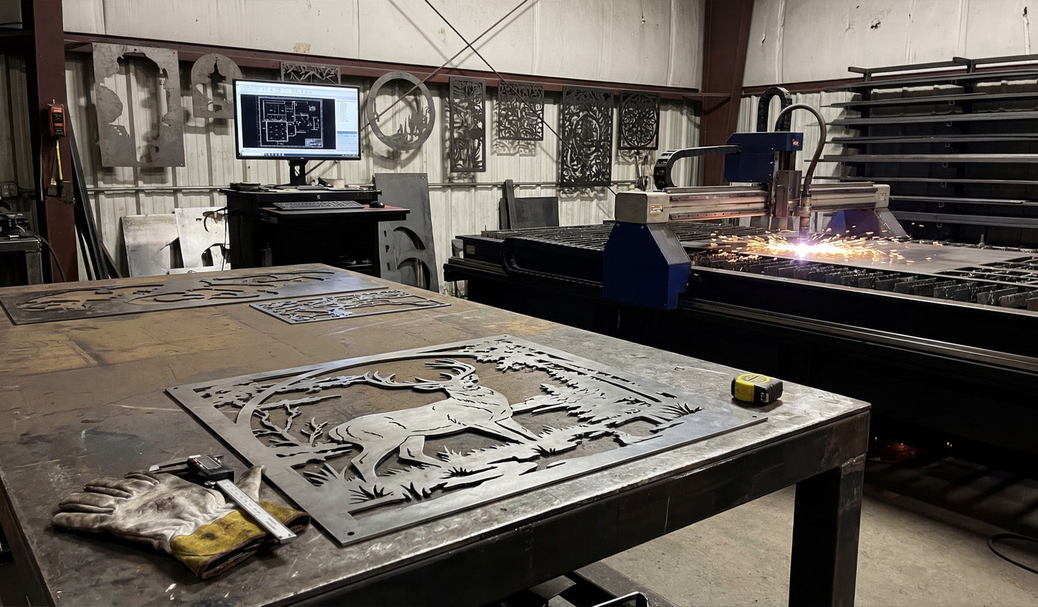
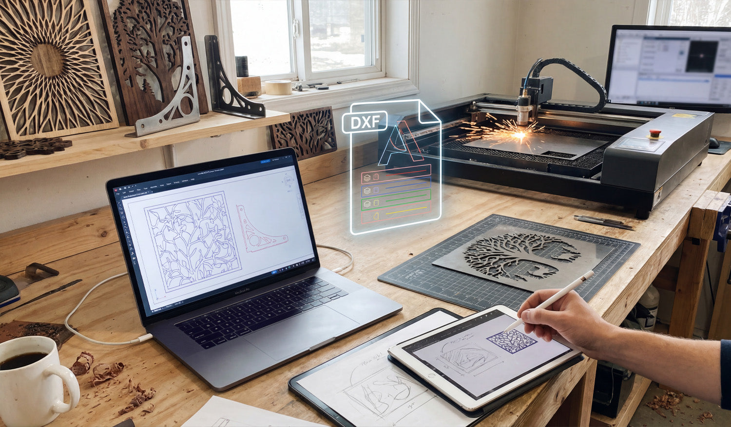
Bridging the gap between a creative spark and a metal masterpiece relies entirely on how well you manage your digital workflow. As shown in the workshop setup above, the journey begins long before the laser fires up; it starts with a sketch, transforms into a precise digital blueprint, and culminates in a flawless cut. Whether you are sketching a custom design on a tablet or fine-tuning vectors on your laptop, understanding the transition from a raw idea to a machine-ready DXF file is the most critical skill for any CNC fabrication business owner aiming for efficiency and profit. 1. From Stylus to Vector: The Design Phase Modern CNC fabrication has moved beyond rigid engineering; it is now an art form. As seen on the tablet in the workspace, many successful projects begin with a simple hand-drawn sketch. Using digital illustration tools allows you to create organic shapes, like the nature-inspired leaf patterns shown on the screens. However, a sketch is just a raster image (pixels). To communicate with your machine, this must be converted into a vector format (lines and arcs). This is where the magic happens—tracing your design to create clean, mathematically defined paths. 2. Decoding the DXF: Layers and Lines The glowing "DXF" icon in the center of the image represents the universal language of CNC machines: the Drawing Exchange Format. A high-quality DXF file acts as the translator between your design software and your laser or plasma cutter. Notice the color-coded layers in the graphic? In professional DXF Designs, different layers are often used to tell the machine to perform different actions—such as engraving the details first (blue/green lines) before performing the outer profile cut (red lines). Organizing your file correctly prevents errors and wasted material. 3. Simulation and Optimization Before you send a file to the cutter, look at the laptop screen. The operator is running a simulation to check the cutting path. This step is non-negotiable. You must ensure that: Nodes are minimized: Too many data points can cause the machine to jitter. Loops are closed: If a shape isn't fully closed, the piece won't drop out of the sheet. Kerf Compensation: You have accounted for the width of the material that the laser or plasma beam burns away. If you are new to this process, we recommend practicing with our Free DXF Files to understand how a clean, optimized file looks and behaves in your software. 4. The Physical Result: Turning Vectors into Income The background of the shop features the ultimate goal: finished, sellable products. The "Tree of Life" wall art and the geometric privacy screens are prime examples of high-demand items in the home decor market. By mastering the digital side of things, you reduce trial and error, meaning you burn less metal and sell more art. For those who want to skip the design phase and go straight to production, our Full Access Bundle offers thousands of ready-to-cut designs that have already been optimized for you. 5. Staying Organized and Legal Just as the workbench is organized with tools ready at hand, your digital library should be equally tidy. Keep your files backed up and sorted by category. Furthermore, always ensure you have the rights to produce the work you are selling. You can review our Legal Usage License Agreement to understand how to use commercial files safely and profitably. Ready to start your next project? Browse our collections or Contact Us if you have technical questions about file compatibility.

Turning DXF Files into Profit: A Complete CNC Plasma Workflow Guide
Operating a successful CNC fabrication business requires more than just owning a machine; it is about mastering the workflow from the digital screen to the finished physical product. Whether you are running a high-definition plasma cutter or a laser machine, the journey starts with a flawless DXF file and ends with meticulous quality control. In this guide, we explore the essential steps to streamline your production process, optimize your cutting parameters to handle intricate designs like scrollwork panels, and ensure that every bent bracket or decorative piece adds real value to your bottom line. 1. It Starts with the Digital Blueprint As seen on the laptop in our workshop, every project begins with software. Before you even touch a sheet of metal, your DXF file must be optimized. Common issues like open vectors, double lines, or excessive nodes can cause your CNC machine to "stutter," leading to rough edges and wasted material. To ensure a smooth cut, always run a simulation in your CAM software. If you are looking to test your machine capabilities without risk, you can download some of our Free DXF Files to practice with high-quality, cut-ready vectors. 2. Mastering the Cut: Plasma and Laser Dynamics The sparks flying in the workshop represent the critical moment of fabrication. When cutting intricate decorative panels—like the scrollwork design shown on the table—precision is key. Here are a few CNC tips to maintain quality: Speed vs. Quality: For detailed art pieces, slow your machine down slightly to minimize dross (slag) on the corners. Pierce Delay: Ensure your pierce delay is set correctly for the material thickness to prevent molten metal from splashing back onto the torch nozzle. Torch Height Control (THC): Keep your THC active. Warping is common in large decorative cuts due to heat; the THC ensures the torch stays at the optimal cutting height despite plate movement. 3. Post-Processing and Quality Control Notice the operator in the photo inspecting a metal bracket? This is arguably the most important step in the business. A CNC machine cuts the part, but the human eye ensures it is sellable. After the cut, your workflow should include: Deburring: Removing sharp edges and dross. Bending and Forming: Many profitable products, like shelf brackets or structural supports, require a press brake operation. Accuracy here depends on the precision of the original DXF cut. Fitment Check: Always measure your first off-the-line part against your specifications before running the rest of the batch. 4. Turning Metal into Marketable Products The finished wooden and metal art pieces in the background of the shop demonstrate the versatility of CNC technology. You aren't just selling metal; you are selling home decor, privacy screens, and functional hardware. By utilizing a wide library of designs, such as those found in our Full Access Bundle, you can instantly expand your product catalog without spending hours on design work. 5. Safety and Shop Organization A productive shop is an organized shop. Keep your raw materials racked safely and your walkways clear. Ensure you have proper ventilation for plasma smoke and proper eye protection for the arc glare. An efficient layout allows you to move from the computer station to the machine, and finally to the assembly table without obstruction. If you have questions about commercial use or specific file types, feel free to review our License Agreement or Contact Us directly.
From Sketch to Steel: The Complete CNC Design Workflow
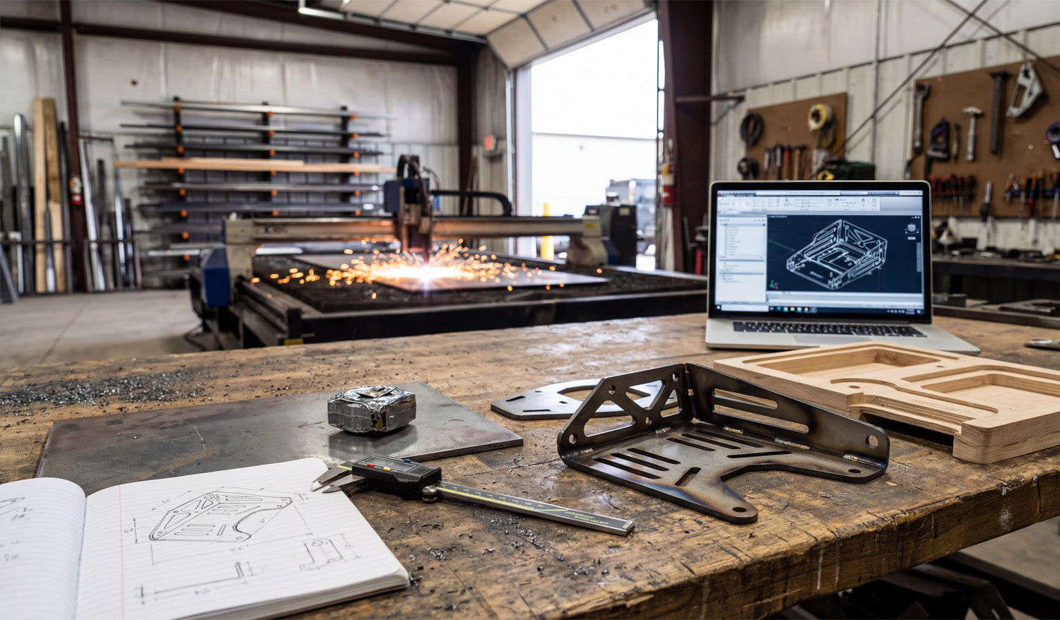
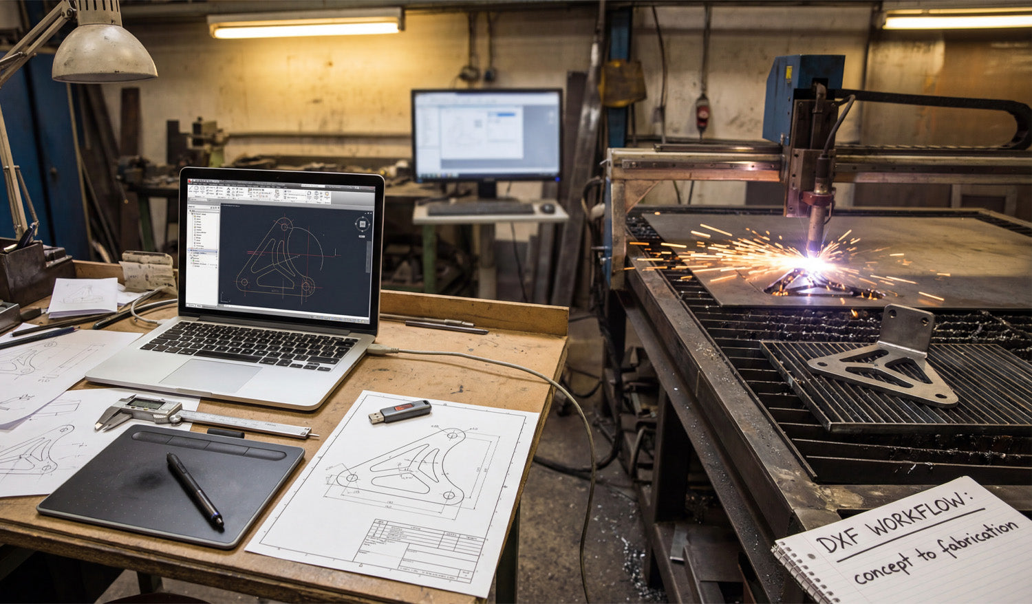
Every successful CNC project begins long before the machine torch fires up; it starts with a concept, often scribbled in a notebook, and evolves through digital verification before becoming a physical reality. The image above perfectly captures the full lifecycle of a custom fabrication project: from the initial hand-drawn dimensions on paper to the 3D CAD model on the laptop, and finally to the sparks flying in the background as the plasma cutter does its work. Understanding this workflow—specifically the transition from a rough sketch to a precision DXF file—is what separates hobbyists from professional fabricators who turn metal into profit. 1. The Power of the Sketch (and the Caliper) Look at the foreground of the workbench. You see a notebook with a hand-drawn diagram and a set of digital calipers. This is the most critical stage. Before you even touch your computer, you need to define your constraints. Whether you are reverse-engineering a broken part or designing a custom bracket for an automotive application, precise measurement is non-negotiable. A variance of just 1mm in your initial sketch can result in a part that doesn’t bolt up, wasting expensive sheet metal. 2. Digital Verification: Why We Prototype One of the most interesting elements in this photo is the wooden prototype sitting next to the finished metal bracket. This is a "CNC Pro Tip" that can save you thousands of dollars. Before cutting expensive steel or aluminum, successful shops often run a test cut using cheap materials like MDF, plywood, or cardboard. This allows you to: Check for physical interference and fitment. Verify that your bend lines are calculated correctly (bend deduction). Ensure the DXF file scale is 1:1. Once the wooden prototype fits, you can confidently send the DXF file to the laser or plasma cutter, knowing the final result will be perfect. 3. From Screen to Steel: The Finished Product The laptop screen shows a 3D model of the bracket, while the finished steel part sits on the table, folded and welded. This complex bracket features slots for adjustability and lightening holes to reduce weight—features that are easy to design in CAD but difficult to make by hand. This is the beauty of CNC technology; it allows for high-complexity parts to be produced repeatedly with zero variance. For those looking to enter the market of selling custom parts, complex brackets like these are high-demand items in the off-road, construction, and interior design markets. You don't always need to reinvent the wheel, though. Having a library of pre-tested designs allows you to skip the drafting phase and go straight to cutting. 4. Streamline Your Workflow If you want to focus more on the "cutting" and less on the "drawing," utilizing high-quality, pre-designed vector files is the key. You can start practicing your workflow today by downloading some of our tested designs from the Free DXF Files section. For serious fabricators ready to equip their shop with a massive catalog of cut-ready designs—from privacy screens to fire pits and brackets—our Full Access Bundle offers an all-in-one solution to keep your machine running and your revenue flowing.
The Precision Standard: Why Clean DXF Files Beat Raster Images Every Time
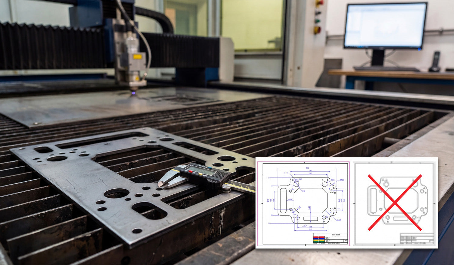
Precision is the currency of the CNC world, and as the photo illustrates, the difference between a profitable part and a piece of scrap metal often comes down to the quality of your source file. Whether you are cutting heavy-duty mounting plates for automotive applications or intricate decorative panels, your CNC machine—be it laser, plasma, or waterjet—relies entirely on the mathematical precision of vector data. Understanding why a "clean" DXF file is mandatory, and why a standard image file simply won't work, is the first step toward achieving the kind of tight tolerances shown by the digital caliper in the image. You Can't Cut Pixels: Vector vs. Raster Look at the overlay graphic in the image. On the right, you see a pixelated, blurry representation of a part (often a JPEG or PNG). On the left, you see a crisp, blue-lined technical drawing (DXF). This is the battle between Raster and Vector. A CNC machine is a blind robot; it follows coordinates, not pictures. If you try to feed it a raster image (made of pixels), the machine sees nothing but noise. It needs a vector file (DXF), which consists of mathematical paths—lines, arcs, and nodes—that tell the torch exactly where to travel. If you attempt to use auto-tracing software on a low-quality image, you often end up with "jagged" lines. This causes your machine to stutter, resulting in rough edge quality and dross buildup that ruins the part. The Caliper Test: Why Accuracy Matters The digital caliper measuring the bolt hole in the photo represents the ultimate test. If your design requires a 10mm hole for a specific bolt, a clean DXF file ensures that the machine cuts a perfect circle at exactly that dimension (accounting for kerf width). When you use poorly optimized files or bad conversions: Circles become ovals: The geometry distorts, making assembly impossible. Dimensions drift: A part meant to be 10 inches wide might come out as 9.9 inches or 10.1 inches due to thick, fuzzy lines in the design phase. Wasted Material: Metal is expensive. Every time you have to re-cut a part because the holes didn't line up, you are throwing money into the scrap bin. Sourcing "Cut-Ready" Files To ensure your business stays profitable, you need to eliminate the guesswork. You should be spending your time cutting and shipping, not fixing broken nodes or open contours in CAD software. Professional fabrication shops rely on verified, engineered DXF libraries to guarantee that what they see on the screen is exactly what comes off the table. If you are looking to test your machine's accuracy with high-quality vectors, you can start by downloading from our Free DXF Files collection. For those ready to access a massive library of verified, commercial-ready designs, our Full Access Bundle offers the reliability you need to put that caliper to work with confidence.
From Screen to Spark: Mastering the CAD to CNC Workflow with DXF Files
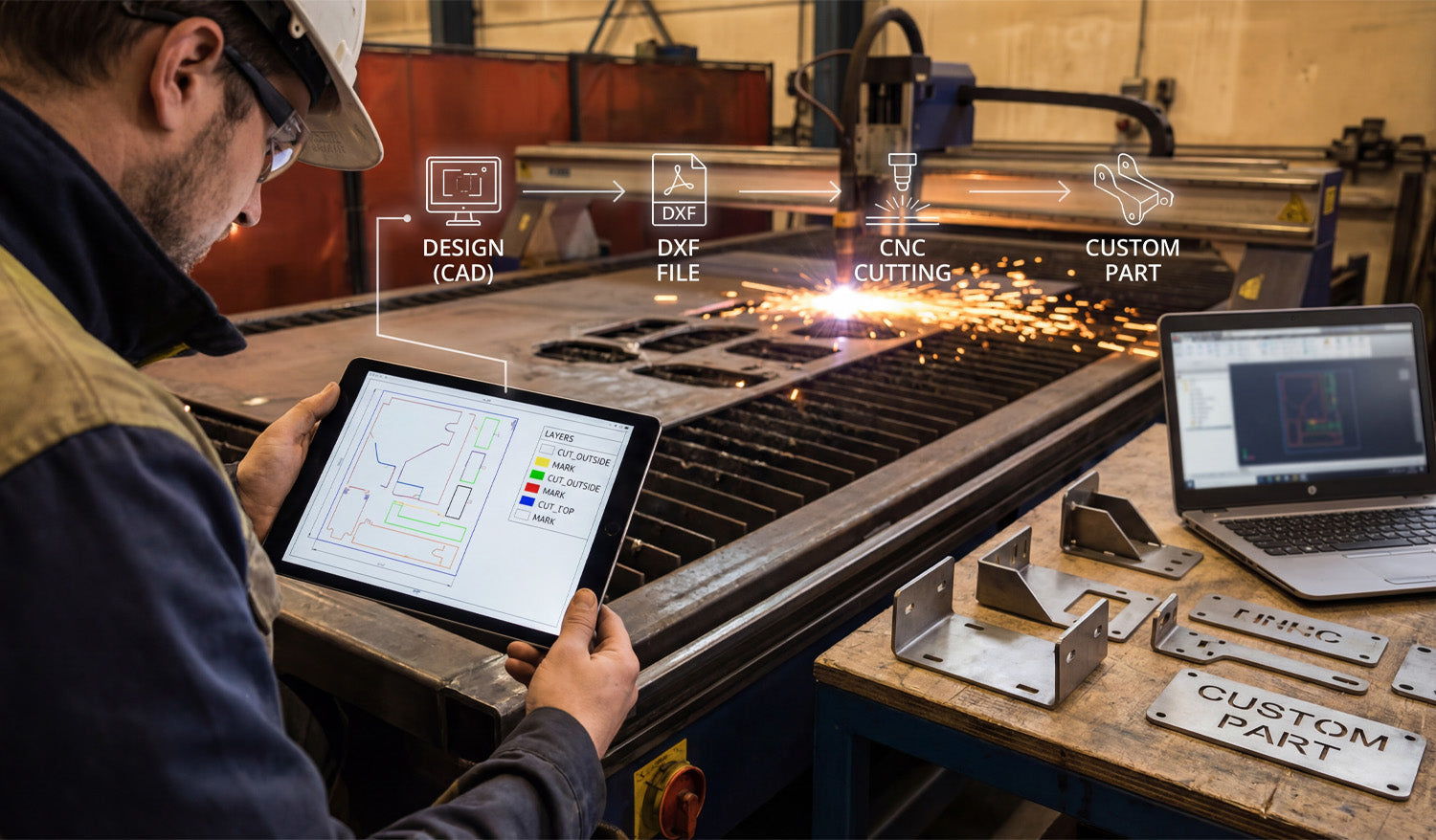
Transforming a digital concept into a tangible metal part is the ultimate goal of every CNC fabricator, yet the gap between a design on a screen and the sparks flying in the shop is often where beginners struggle. The process requires a seamless transition from the initial CAD design to a clean DXF file, and finally to the CNC machine that executes the specific cutting or marking commands. By understanding how to organize your digital layers and optimize your files, you ensure that your plasma or laser cutter operates efficiently, reducing wasted material and maximizing profit on every custom part you produce. The 4-Step Workflow: From Idea to Industrial Part As shown in the workflow graphic above, successful fabrication isn't magic; it is a structured process. Whether you are running a garage workshop or a full-scale industrial operation, the path remains the same: 1. Design (CAD): It starts with imagination and geometry. Using CAD software, you define the dimensions and shape of your part. This is where accuracy counts the most. 2. DXF File Creation: This is the universal language of CNC. Converting your design to a DXF (Drawing Exchange Format) bridges the gap between your computer and the machine controller. 3. CNC Cutting: The machine interprets the vector data from the DXF. If the file is clean, the torch or laser follows the path precisely. 4. The Custom Part: The result is a physical product—like the heavy-duty brackets shown on the workbench—ready for assembly or sale. Why Layering Matters: A Look at the Tablet If you look closely at the tablet in the image, you will see a crucial detail that separates amateurs from pros: Layer Management. The screen displays different colors for different operations (Yellow for "MARK", Green/Blue for "CUT_OUTSIDE"). Your CNC machine needs to know the difference between cutting a hole through the material and simply etching a part number or bend line onto the surface. By separating these geometries into specific layers within your DXF file, you tell the CAM software exactly what to do. Pro Tip: Always set your cut order to etch/mark first, cut interior holes second, and cut the exterior perimeter last. This prevents the part from shifting on the table before the internal work is finished. Turning Sparks into Profit The brackets and custom parts sitting on the table in the photo represent revenue. In the world of CNC, time is money. Every minute you spend fixing bad nodes or unconnected lines in a DXF file is a minute the machine isn't cutting. To scale your business, you need a library of files that are "cut-ready." This allows you to say "yes" to clients faster and move straight to production. Whether you are selling automotive brackets, custom signage, or structural components, the quality of your source file dictates the quality of your product. For those looking to skip the design headache and start cutting immediately, accessing a verified library is a game changer. You can explore our vast collection of designs in our Full Access Bundle, which provides thousands of tested, layer-optimized files ready for your machine. Start with the Right Files If you are new to this workflow, don't be intimidated. Start by testing your machine's settings with simple geometries. You can practice with reliable designs by downloading from our Free DXF Files section. Mastering the link between the "Design" and the "Cut" is the most valuable skill you can develop in the CNC industry.
Why DXF is the Gold Standard for CNC Cutting: Precision and Compatibility
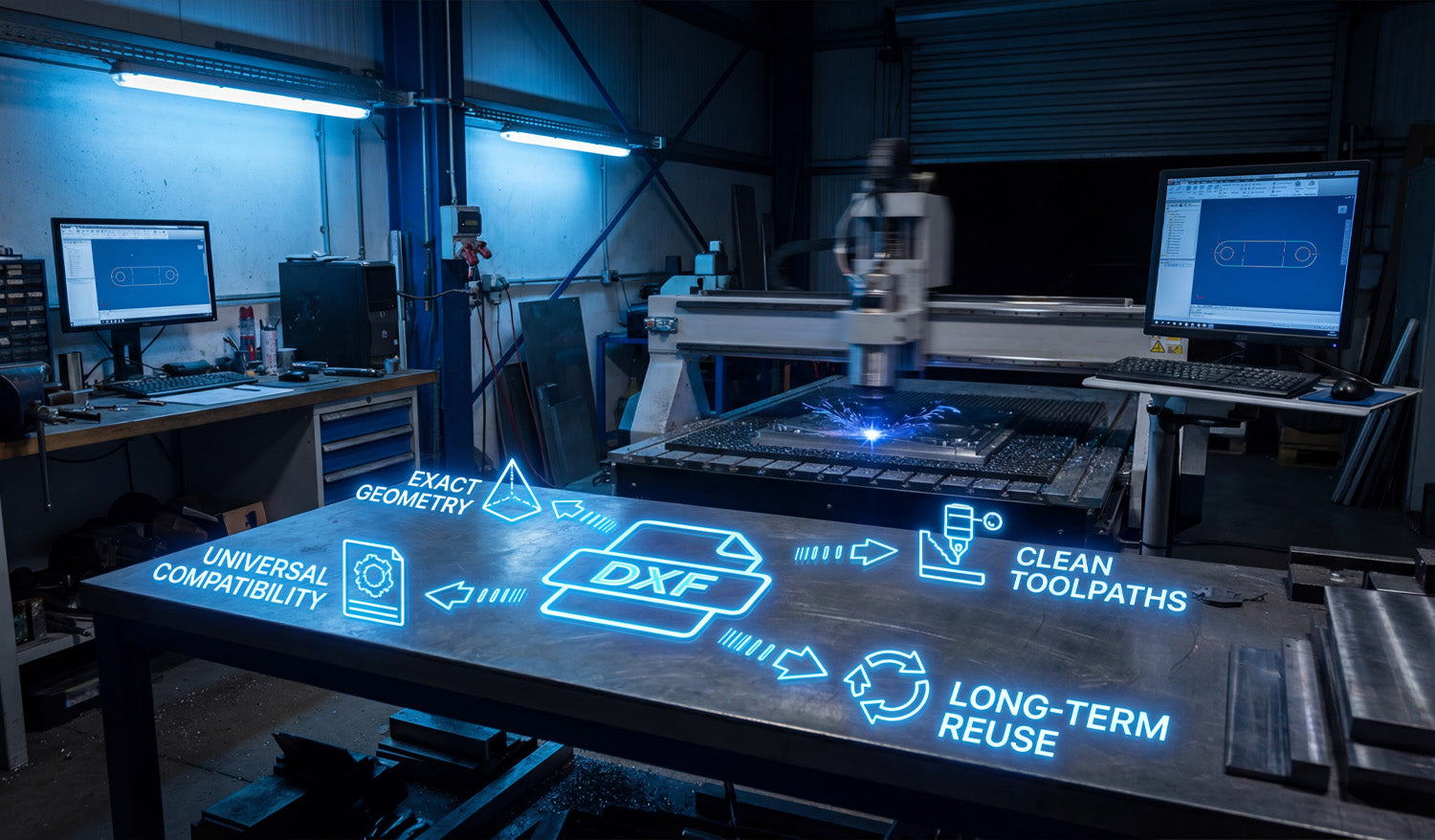
Success in CNC machining doesn't start when the spark hits the metal; it starts the moment you choose your file format. In the world of digital fabrication—whether you run a plasma cutter, laser, or waterjet—the DXF file is the heartbeat of your operation. It bridges the gap between a creative idea and a physical industrial part. Choosing high-quality, clean DXF files ensures your machine runs specific toolpaths without errors, saving you time, electricity, and expensive materials. 1. Universal Compatibility: The Language of CNC One of the biggest struggles for new CNC owners is software compatibility. You might design in Fusion 360, but your machine controls run on SheetCam or LightBurn. The beauty of the DXF (Drawing Exchange Format) is its Universal Compatibility. It is the industry-standard vector format that acts as a universal translator. Regardless of the brand of your CNC table or the software you use to generate G-code, a standard DXF file will import correctly. This flexibility allows you to focus on cutting rather than troubleshooting file types. If you are just starting out and want to test how your software handles these files, you can try some of our Free DXF Designs to see this compatibility in action. 2. Exact Geometry: Scaling Without Loss Unlike image files (JPG or PNG) which are made of pixels, DXF files rely on Exact Geometry defined by mathematical vectors. This is crucial for fabrication shops. Imagine you have a file for a decorative wall art piece. With a DXF, you can cut that design as a small 10-inch coaster or scale it up to a massive 10-foot intricate driveway gate. The lines remain perfectly smooth, and the arcs stay true curves. You never have to worry about "pixelation" or jagged edges that require hours of manual grinding and finishing after the cut. 3. Clean Toolpaths for Efficient Production A DXF file is only as good as the designer who drew it. High-quality files provide Clean Toolpaths. This means: No Open Contours: The cut path is continuous, so the torch doesn't stop unexpectedly. No Overlapping Lines: Prevents the machine from cutting the same area twice, which ruins the workpiece. Optimized Lead-ins/Lead-outs: Ensures the pierce point doesn't damage the visual quality of the part. Using files that are pre-optimized for cutting means you spend less time fixing nodes in your CAD software and more time making money with your machine. 4. Long-Term Reuse: Building Your Digital Assets Think of your DXF files not just as consumables, but as Long-Term Reuse assets. Once you have a clean, proven file, it becomes a permanent part of your digital inventory. A customer might order a custom fire pit today, and three years from now, another customer might want the exact same design. Having a library of reliable files allows you to say "Yes" to orders instantly without re-doing the design work. For shops looking to secure a massive library of ready-to-cut assets instantly, our Full Access Bundle offers a complete catalog that creates immediate business value. Conclusion Your CNC machine is a powerful tool, but it relies on efficient data to perform at its best. By utilizing DXF files that prioritize exact geometry and clean toolpaths, you reduce waste and increase profitability. Whether you are cutting mechanical brackets or artistic signs, the right file makes all the difference.
From Concept to Fabrication: Mastering the DXF Workflow for CNC Cutting
Turning a rough sketch into a precision-cut metal part is the core of any successful CNC business or hobbyist workshop. In this guide, we break down the essential DXF workflow—from initial design and digital drafting to the final sparks on the cutting table—ensuring your projects move seamlessly from concept to fabrication without costly errors. Step 1: The Concept and Measurement Every great project starts with an idea. As seen in the workshop workflow, it often begins with a simple pencil sketch on paper. Whether you are designing a custom automotive bracket or a decorative metal panel, accuracy is paramount right from the start. Using calipers to get precise measurements of bolt patterns and dimensions is crucial. If you are new to designing or simply looking for inspiration without doing the math, you can start by exploring our free DXF designs. These files are ready to cut and can help you understand how a proper digital design correlates to a physical object. Step 2: Digitization and DXF Optimization Once you have your measurements, the next step is transferring that data into CAD/CAM software. This is the bridge between the physical and digital worlds. In the workspace, the laptop screen displays a 2D wireframe of the part. This is where you create your DXF file. Expert Tip: When saving your design as a DXF, ensure your vectors are clean. This means: Closed Loops: Make sure all shapes are fully closed so the CNC machine knows exactly where the material creates a solid part. No Overlapping Lines: Duplicate lines can confuse the cutter, leading to jagged edges or double cuts. Kerf Compensation: Remember that the laser or plasma beam has a width. Your design software should account for this to ensure the final part fits perfectly. Step 3: From File to Fire (Fabrication) After verifying your DXF file, it’s time to send it to the machine controller. This is where the virtual design becomes reality. As the plasma or laser cutter engages the metal, accuracy relies entirely on the quality of your input file. A clean DXF ensures smooth motion, reduced dross (slag), and a professional finish. For shops looking to maximize efficiency and skip the design phase entirely to focus on production and sales, our Full Access Bundle offers a massive library of verified, cut-ready files. This allows you to keep your machine running and generating revenue without spending hours in front of a computer screen. Monetizing Your Workflow The bracket shown in the workflow isn't just a piece of metal; it's a product. Custom fabrication is a booming market. By mastering the DXF workflow, you can produce: Custom automotive mounts and suspension parts. Heavy-duty shelving brackets for industrial use. Bespoke machinery replacement parts. Understanding this process from "Concept to Fabrication" empowers you to say "yes" to more client requests and grow your business. For more details on how you can use our files commercially, please review our License Agreement.

