CNC & DXF Design Guides
CNC & DXF Design Guides
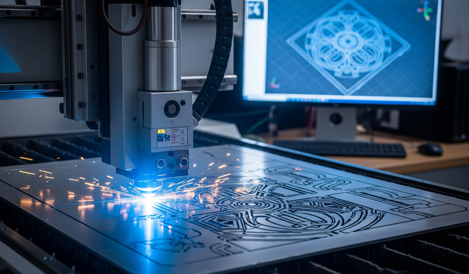
Precision Laser Cutting: Transforming Complex DXFs into Metal Art
There is a specific thrill in watching a CNC laser machine execute a complex design. As the cutting head dances fast across the sheet metal, throwing sparks and leaving behind a perfectly crisp edge, you are witnessing the perfect synchronization of hardware and software. However, as shown in the image above, that beautiful physical cut—glimmering with sparks—is entirely dependent on the blue wireframe displayed on the monitor in the background. If your digital file is flawed, your machine will fail. In high-end metal fabrication, the line between a scrapped sheet of expensive steel and a profitable piece of art is drawn by the quality of your DXF file. The "Digital Twin" Concept Look at the relationship between the computer monitor and the cutting bed in the photo. The complex mandala design on the screen is the "Digital Twin" of the part being cut. For the machine to replicate that intricate geometry without error, the DXF file must be mathematically perfect. This means: Closed Loops: Every shape must be a continuous path. No Overlaps: Double lines confuse the laser, causing it to cut the same path twice, ruining the edge and overheating the material. Node Reduction: Too many nodes (data points) can cause the machine to "stutter," leading to jagged edges instead of smooth curves. To ensure your projects run this smoothly, we recommend starting with verified designs. You can test your machine’s calibration with our Free DXF Files before moving to larger sheets. Managing Heat and Deformation The sparks flying in the image represent intense heat. When cutting dense, intricate patterns like this geometric medallion, "Thermal Distortion" becomes a real risk. If your DXF file isn't optimized, the laser might cut too much detail in one small area at a time, warping the metal. Professional DXF files are designed to allow for proper spacing. Furthermore, inside your CAM software, you should utilize "cut path optimization" to spread the heat across the sheet. This ensures the piece stays flat and the dimensions remain accurate. Monetizing Complex Art Why go through the trouble of cutting such complex designs? Because that is where the profit lies. Simple squares and circles are easy, but intricate decorative panels, privacy screens, and custom wall art command high prices in the home decor market. The design shown in the photo is a prime example of a high-value item that can be sold for hundreds of dollars, despite low material costs. By investing in our Full Access Bundle, you gain instant access to a library of complex, high-margin designs that are ready to cut. We have done the hard work of designing so you can focus on the manufacturing and selling. Safety and Licensing As you scale up your production of these artistic pieces, remember that protecting your business is as important as protecting your eyes from the laser. Always ensure you have the right to sell the physical goods you produce. You can review our transparent License Agreement to cut with confidence. If you encounter issues with cut quality or software import errors, our FAQ Page is an excellent resource to troubleshoot common CNC problems. Keep your lens clean, your files cleaner, and let the sparks fly!
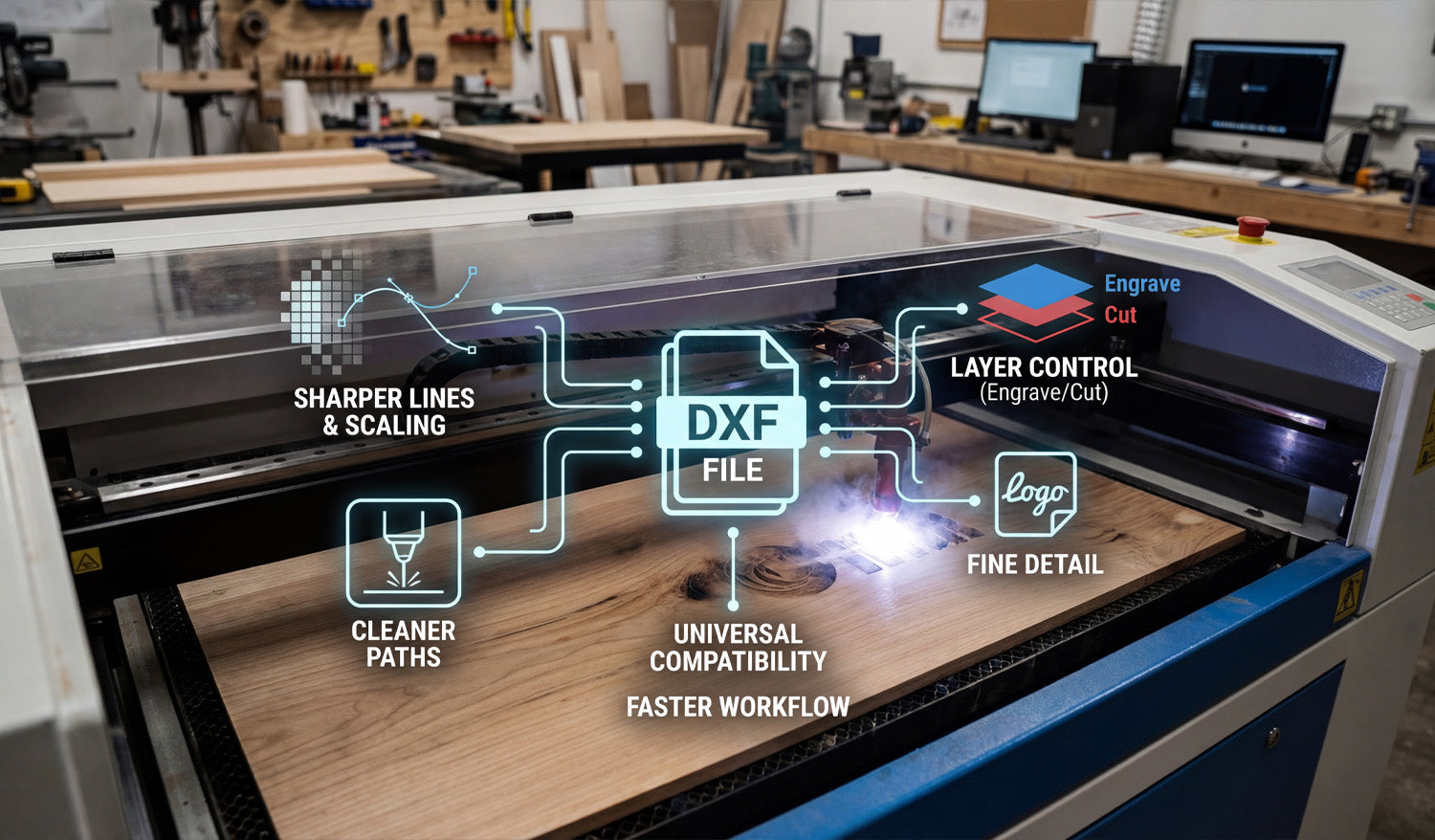
Why You Should Use DXF Files for Your CNC Laser Engraving Projects
Using DXF files for your CNC laser engraving projects makes it easier to get crisp details, clean lines, and repeatable results while keeping your workflow simple and efficient. What Is a DXF File in Laser Engraving? DXF (Drawing Exchange Format) is a 2D vector file type that stores shapes as lines, arcs, and curves instead of pixels. For CNC laser engraving, this means your design is made of precise paths that the machine can follow directly, rather than a blurry image the software has to guess from. DXF files are supported by most CAD, graphics, and CAM programs, which makes them a natural “universal language” for CNC laser engravers. Reason 1: Sharper Lines and Unlimited Scaling One of the biggest advantages of using DXF files for laser engraving is that vector geometry never becomes pixelated or fuzzy. Crisp engravings: Lines and curves stay sharp at any size because they are defined by math, not pixels. Unlimited scaling: You can resize artwork for small keychains or large wall panels without losing quality. Consistent detail: Thin outlines, logos, and text stay clean and readable when designed correctly. If you have ever tried to engrave a low-resolution JPG and been disappointed with jagged edges, switching to DXF-based artwork is a big upgrade. Reason 2: Cleaner, Faster Engraving Paths DXF files describe exact paths, which helps your laser engraver move more efficiently. Smooth motion: Clean curves and polylines let the laser head move at a steady speed, improving engraving quality. Less back-and-forth: Vector paths can be optimized in CAM to reduce wasted travel and overlapping passes. Shorter job times: Efficient paths mean the laser spends more time engraving and less time repositioning. By starting with a clean DXF file, you give your CAM software the best possible data to generate compact, efficient engraving toolpaths. Reason 3: Easy Control Over Engrave vs Cut CNC laser projects often mix engraving and cutting in a single job—engrave a logo, then cut out the outer shape. DXF files make this easy to manage. Layers for operations: Put engraving lines on one layer and cut lines on another so they can use different power and speed settings. Color mapping: Many laser controllers let you assign different colors in the DXF to different power levels and passes. Safer workflow: Clear separation means you are less likely to accidentally cut where you only meant to engrave. With a well-organized DXF file, you can control every part of the design—deep cuts, light scoring, and filled engraving—using simple layer or color settings. Reason 4: Better Text, Logos, and Fine Detail Text and logos are at the heart of many laser engraving projects: nameplates, awards, signs, ID tags, and branded products. DXF files handle these elements very well. Editable vector text: You can adjust size, spacing, and fonts in CAD or vector software, then convert text to outlines for reliable engraving. Logo accuracy: Company logos and icons can be traced or drawn as vectors and stored in DXF format for long-term use. Fine line control: You can define stroke thickness and spacing in detail so small elements engrave cleanly without filling in. Because DXF files are based on vectors, even very small text and thin lines can remain readable when engraved at the right scale. Reason 5: Consistent Results Across Different Lasers As your workshop grows, you may use different brands or sizes of CNC laser engravers. DXF files help keep your designs portable and consistent. Universal format: Most laser software can import DXF, regardless of machine brand. Same artwork, different settings: You can reuse the same DXF file and simply adjust speed, power, and frequency for each machine or material. Easier outsourcing: If you send work to another shop, DXF files are widely accepted and easy to use. This portability means your artwork library stays useful even if you upgrade machines or add new equipment later. Reason 6: Flexible Design Edits and Personalization Many CNC laser engraving projects are customized: names, dates, serial numbers, or personalized messages. DXF-based workflows make these changes simple. Quick text changes: Edit names or messages directly in your CAD/vector program and re-export the DXF. Modular layouts: Keep fixed artwork (logos, borders) as one DXF and swap in different nameplates or text blocks as needed. Batch personalization: Set up templates where only a small part of the DXF changes from job to job. This approach is ideal for engraving businesses that produce repeat designs with unique customer details. Reason 7: Smaller File Sizes and Easier Storage Complex image engravings can create very large raster files. DXF files, being vector-based, stay relatively compact even with detailed designs. Efficient storage: Large design libraries take up less space when stored as DXF. Faster loading: Laser software can often load vector DXFs faster than high-resolution bitmaps. Simple backups: Smaller files are easier to back up and sync between computers or cloud storage. Over time, a well-organized DXF library becomes a high-value asset that is easy to maintain and move between systems. How DXF Files Fit into a Typical Laser Engraving Workflow Here is how DXF files usually plug into a CNC laser engraving process: Create or edit artwork: Design your layout in CAD or vector software (text, logos, borders, frames). Organize layers and colors: Separate engraving and cutting paths into different layers or colors. Export as DXF: Save or export the design in DXF format. Import into laser software: Open the DXF, assign power/speed settings to each layer or color, and position the design on the material size. Simulate and preview: Check the order of operations and verify scale. Engrave and cut: Run a test on scrap material if needed, then engrave the final piece. Common Mistakes When Not Using DXF (or Using It Poorly) Understanding what can go wrong helps you see why clean DXF files are valuable: Low-resolution images: Engraving small JPGs can lead to fuzzy edges and unreadable text. Unscaled artwork: Designs imported at the wrong size cause cramped layouts or wasted space. No layer separation: Cutting and engraving lines mixed together increase setup time and risk mistakes. Messy vectors: Auto-traced files with too many nodes can slow down engraving or cause jittery motion. By investing a little time to prepare clean DXF artwork, you avoid these problems and get more consistent results. Checklist: Is Your DXF Ready for CNC Laser Engraving? Before sending a job to your laser engraver, run through this quick DXF checklist: ✔ The design is vector-based, not just a low-res image. ✔ All important outlines and text are converted to curves and scale correctly. ✔ Engraving and cutting paths are on separate layers or colors. ✔ Detail level matches your material and lens (no micro details that will burn away). ✔ There are no duplicate or overlapping lines where you only want a single pass. ✔ Text, logos, and fine elements look clear at the final size you plan to engrave. Conclusion DXF files are one of the best foundations you can use for CNC laser engraving projects. They give you crisp lines, infinite scaling, clean engraving paths, and flexible control over cutting versus engraving—all in a format that works across most CAD, CAM, and laser systems. Whether you are engraving custom gifts, branded products, signs, or industrial labels, building your workflow around DXF files will make your jobs faster, cleaner, and more consistent on every CNC laser engraver you use.
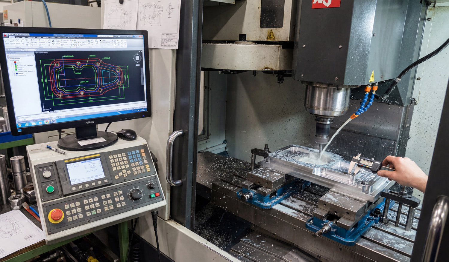
Using DXF Files for Complex CNC Milling Projects
Using DXF files for complex CNC milling projects gives you a clean way to define profiles, pockets, and critical 2D geometry so your CAM software can generate accurate toolpaths for multi-step, multi-setup machining. How DXF Files Fit into Complex CNC Milling Work CNC milling is more than simple outlines. Real projects often include: Multiple pockets at different depths. Step faces and 2.5D contours. Bolt patterns, slots, and precision holes. Parts that require multi-side machining (top, bottom, and edges). DXF (Drawing Exchange Format) files are ideal for describing the 2D geometry behind those features—profiles, boundaries, and reference curves that your CAM system uses to drive roughing and finishing toolpaths. DXF vs 3D Models in CNC Milling Many complex milling projects use both 3D models and DXF files together. 3D models (STEP, IGES, etc.): Define full solid shapes and surfaces for complex 3D machining. DXF files: Define precise 2D outlines, pockets, and hole patterns for profiling and 2.5D operations. Even if you work from a full 3D model, exporting critical views as DXF—for example, the top profile or bolt circle—can make it easier to create and control specific milling operations in CAM. Planning Complex Milling Projects with DXF Geometry Before you start drawing or importing DXF files, think through the overall milling strategy. Setup plan: How many setups will you need (top only, top and bottom, or multiple sides)? Zero and origin: Where will your work coordinate system (WCS) be? Corner, center, or a feature? Feature groups: Which features are roughing only, which are precision, and which can be cut in a single operation? Tools and holders: What tool diameters and lengths will be used for each area? Once you have a plan, you can build or clean DXF geometry that directly supports that strategy instead of fighting against it. Creating DXF Files for Profiles and Pockets In complex CNC milling, DXF files are especially useful for defining: Outer profiles: The final outside shape of the part as viewed from the top. Inner pockets: Closed contours that mark where material should be removed to a certain depth. Bosses and islands: Areas that should stay at a higher level inside a pocket. Slots and keyways: Long, narrow cutouts used for mechanical function. Each of these can be drawn or exported as clean, closed 2D loops that your CAM software recognizes as milling regions. Layering DXF Geometry for Complex Operations Using layers in your DXF file makes it much easier to handle multiple depths, tools, and strategies. Place outer profiles on one layer (for example, PROFILE_OUTSIDE). Place pockets at depth 1 on another layer (for example, POCKET_Z-5). Place deeper pockets or step faces on separate layers (for example, POCKET_Z-10). Place drill holes and bolt circles on a HOLES layer. Use a REFERENCE layer for centerlines, datums, and construction geometry that should not be cut. When you import the DXF into CAM, you can map each layer to a different operation and depth, which speeds up programming and reduces mistakes. Designing DXF Geometry with Tool Diameter and Corner Radii in Mind CNC milling tools are round, so your DXF design must respect tool diameter and minimum radius limits. Inside corners: Use fillets with a radius at least equal to (and often slightly larger than) the smallest tool radius you plan to use. Slots and pockets: Make sure the width is comfortably larger than your tool diameter so the cutter has room to clear chips. Sharp transitions: For precision fits, consider adding small relief pockets or “breakout” radii where mating parts need clearance. Drawing these features correctly in DXF reduces the need to “cheat” toolpaths in CAM and helps you hold tolerances more easily. Using DXF for Multi-Setup and Multi-Side Milling Complex milling jobs often require machining from more than one side. DXF files can help you manage this. Top view DXF: Defines top profiles, pockets, and drilling layouts. Bottom view DXF: Represents flip-side operations, such as back-side pockets and relief cuts. Side view DXFs: For parts that need machining on the sides, simple 2D side profiles can guide slotting or step cuts. By developing a set of DXF views tied to your setup plan and workholding, you can keep each operation clear and reduce alignment errors between sides. DXF-Based Hole Patterns and Bolt Circles Complex CNC milling projects often include many holes and bolt patterns that must align perfectly with other parts. Use DXF to define exact hole locations based on true dimensions and references. Draw bolt circles with centerlines and a reference diameter so your CAM software can apply drilling or circular pocketing easily. Keep hole types (clearance, tap, dowel) organized on separate layers if they require different tools or cycles. Clear hole geometry in DXF allows CAM to generate drilling, reaming, and countersink operations quickly and consistently. Preparing DXF Files for Rest Machining and Finishing Passes On complex parts, you may rough with a larger tool and finish with a smaller one. DXF boundaries can drive these steps. Define rest machining regions as DXF contours where the larger tool cannot reach (tight corners and small pockets). Use separate layers for finishing boundaries so CAM can apply light, precise finishing passes only where needed. For critical surfaces, create offset boundaries that represent specific finish zones or tolerance areas. This gives you fine control over where extra machining effort is spent, improving both surface finish and cycle time on complex parts. Ensuring DXF Precision: Tolerances and Scaling For complex milling, dimensional accuracy is critical. Your DXF must reflect true sizes and tolerances. Work in the correct units (mm or inches) and double-check overall dimensions. Use precise dimensions in CAD and avoid rounding key features without a reason. Include reference dimensions or a known-length line (for example, exactly 100 mm) to verify scale inside CAM. Document any intentional offsets (for press fits, sliding fits, or adhesive space) so CAM programmers know why the DXF differs from nominal print values. A clean, accurately scaled DXF reduces guesswork and helps you hit target tolerances on the real part. Common DXF Mistakes in Complex CNC Milling Even advanced users run into issues when preparing DXF files for complex projects. Watch out for: Open contours: Profiles or pockets that are not fully closed, confusing CAM’s pocketing and profiling algorithms. Duplicate lines: Overlapping geometry that causes extra passes and poor surface finish. Unclear layer names: Layers called “Layer1” or “default” that do not explain their purpose. Ignoring tool access: Tight features that a real tool and holder cannot reach without collision. No datum references: DXFs that lack clear origin points or datums for aligning multi-setup operations. Building a Reusable DXF Library for Complex Milling Over time, your best DXF files become building blocks for future projects. Save proven pocket shapes, joints, bolt circles, and fixtures as reusable DXF components. Organize them by category—structural, decorative, fixture, etc.—for quick access. Document recommended tools and feeds/speeds that pair well with each standard feature. Reuse and adapt existing DXF geometry for new projects instead of starting from zero. This approach speeds up CAM programming, improves consistency between jobs, and helps new team members follow established milling practices. Conclusion Using DXF files for complex CNC milling projects is a powerful way to control profiles, pockets, hole patterns, and multi-setup operations with precision. By designing clean, layered 2D geometry that respects tool diameter, corner radii, and real-world tolerances, you give your CAM software a strong foundation for efficient toolpaths. Over time, a well-organized DXF library becomes a key asset—helping you program faster, hold tighter tolerances, and deliver complex milled parts with confidence and repeatability.

