CNC & DXF Design Guides
CNC & DXF Design Guides
From Sketch to Steel: The Ultimate CNC Workflow Guide
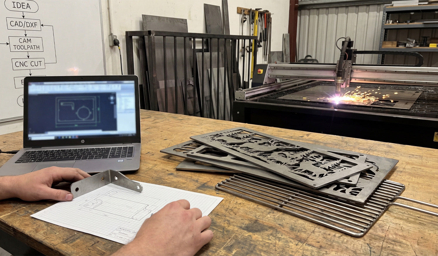
Turning a simple idea scribbled on graph paper into a precise steel component is the ultimate satisfaction in the world of metal fabrication. Whether you are holding a functional prototype bracket or creating intricate decorative metal art, the process relies on a proven workflow: Concept, CAD/DXF Design, CAM Toolpath, and finally, the CNC Cut. Mastering this bridge between the digital and physical worlds is what separates hobbyists from professional fabricators, allowing users to transform raw steel sheets into valuable, sellable products. 1. The Roadmap: Understanding the CNC Workflow As seen on the whiteboard in our workshop, the path to a successful cut follows a strict logic. It begins with an IDEA. This is often just a rough sketch on paper where you calculate dimensions and bend lines. The next step is the most critical: CAD/DXF. To communicate with your machine—whether it's a plasma cutter, laser, or waterjet—you must convert that sketch into a vector file. The DXF (Drawing Exchange Format) is the industry standard here. It serves as the universal language that translates your vision into mathematical coordinates that the computer understands. 2. CAD to CAM: The Invisible Bridge Once you have your clean DXF file, the process moves to CAM (Computer-Aided Manufacturing). This is where you define your "Toolpath." You tell the software how fast to move, where the lead-ins and lead-outs should be, and confirm the kerf width. In the photo, you can see the laptop running simulation software. This step is vital to prevent wasting expensive metal. A well-optimized DXF file ensures that your CAM software doesn't choke on open vectors or intersecting lines, making the transition to the CNC CUT seamless. 3. Prototyping vs. Production There is a distinct difference between fabricating a one-off part and mass production. In the foreground of the image, holding a bent metal bracket against the original graph paper sketch represents prototyping. This ensures the fitment is correct before running a batch of 100. Conversely, the decorative deer panels and grill grates on the workbench represent production products. These are high-value items that are ready for the consumer market. Using high-quality, pre-tested designs eliminates the trial-and-error phase, allowing you to go straight to cutting and selling. 4. Monetizing Your Machine For shop owners, time is money. Drawing every single file from scratch reduces your machine's billable runtime. Utilizing a library of ready-to-cut designs allows you to say "yes" to more customers and fill your shop with diverse inventory, from fire pits to wall art. If you are just getting started and want to test your machine's capabilities, check out our collection of Free DXF Files. For those ready to scale their business with thousands of proven designs, our Full Access Bundle provides a lifetime of creative resources. Conclusion From the spark of the plasma torch to the final bend of the metal, the CNC process is an art form rooted in technical precision. By mastering the workflow from "Idea to Cut," you unlock the full potential of your machinery.
From Sketch to Scale: Prototyping and Nesting for CNC Success
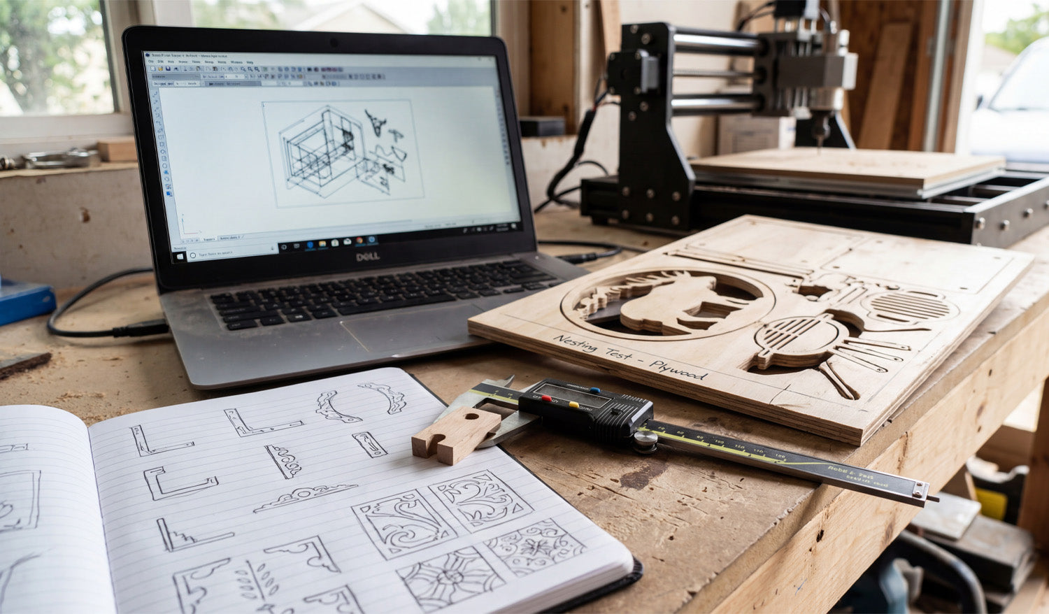
Every great CNC project begins long before the spindle starts spinning; it begins with a concept and a measurement. As captured in the photo above, the journey from a hand-drawn sketch in a notebook to a precision-cut part on the table is the heartbeat of a successful workshop. Whether you are a hobbyist making gifts or a professional optimizing a production run, understanding the transition from "Analogue Sketch" to "Digital DXF" to "Physical Prototype" is essential. Today, we are breaking down the prototyping workflow that saves you time, material, and money. 1. The Sketch: Where Innovation Starts Look at the open notebook in the foreground. Before opening any CAD software, professional designers often sketch their ideas on paper. This helps visualize corner details, joinery, and aesthetics. However, a sketch is not a file. To turn those drawings into reality, you need to convert them into clean vector paths. If you aren't an expert at drawing in CAD yet, you can skip this step by using our Full Access Bundle. We provide thousands of pre-designed, ready-to-cut files that replace the need for hours of sketching and digitizing. 2. The Nesting Test: Maximizing Material The most important detail in this image is the piece of plywood on the table labeled "Nesting Test - Plywood." This is a pro move. "Nesting" is the process of arranging multiple parts (like the elk silhouette and the grill components) as tightly as possible to minimize waste. Notice how the cutouts are placed close together? By running a test cut on cheap plywood, the operator verifies that the spacing is correct and that the tool doesn't accidentally cut into a neighboring part. Never commit to expensive hardwoods or acrylics until you have verified your nesting efficiency on a scrap piece. 3. Verification: The Calipers Don't Lie Sitting right on top of the notebook are digital calipers measuring a small wooden component. In the CNC world, we have a saying: "Trust the file, but verify the part." Before you run a full batch of 50 units, always cut one single prototype. Use your calipers to check the thickness of the material and the depth of the slots. If your material is 0.5mm thicker than your file accounts for, your joinery will fail. Adjust your DXF file or your Z-zero setting accordingly. If you are running into fitment issues, our FAQ Page offers tips on troubleshooting common dimensional errors. 4. The Efficient Workflow The laptop in the background links the sketch to the machine. It shows the wireframe (the DXF) that drives the router. A clean digital workspace leads to a clean physical product. Keep your files organized, check your scale, and categorize your designs. If you are ready to start practicing your own nesting and prototyping, download a few designs from our Free DXF Files collection. Sketch it, cut it, measure it, and perfect it.

From Design to Reality: The Workflow of Functional CNC Parts
The gap between a digital drawing and a functional steel part is often measured in thousandths of an inch. As captured in the photo above, the modern CNC workshop needs more than just a plasma cutter and a laptop; it requires a culture of verification. The scene shows the complete lifecycle of a functional part: the 3D concept on the screen, the 2D technical drawing on the desk, the precise measurement tools, and the violent, spark-filled reality of the cut. Today, we are discussing how to bridge the gap between "drawing lines" and "manufacturing parts." The Trinity of Precision: Digital, Paper, and Steel In the image, you see three distinct versions of the same bracket. Understanding the relationship between these three is the key to minimizing scrap metal in your bin. The Digital Model (Laptop): The screen displays a 3D isometric view of a bracket with holes. However, your CNC machine only reads 2D coordinates. Investing time in "unfolding" your designs correctly into a flat DXF pattern is critical. The Blueprint (Paper): You might ask, "Why use paper in a digital age?" The paper sketch on the bench serves as a quick visual reference for the operator. It highlights critical dimensions that can't be seen in the G-Code. The Reality (The Cut): In the background, the plasma torch is doing the heavy lifting. But as shown by the digital calipers on the desk, the job isn't done until the part is measured. A DXF file is only as good as the machine's calibration. From 2D Cut to 3D Functional Part The bracket shown on the screen and on the table is a bent part. This introduces a layer of complexity to your DXF files called "Bend Allowance." When you cut a flat DXF file intended for folding, you must account for the metal that is stretched during the bending process. If you are new to creating functional parts, we recommend downloading some simple geometries from our Free DXF Files collection to test how your specific machine handles tolerances on holes and slots before moving to complex assemblies. The Business of Functional Parts While artistic gates and signs are beautiful, functional parts like the bracket in this photo—used for construction, automotive mounts, or machinery repairs—are often the most consistent revenue stream for a CNC shop. These parts require strict adherence to dimensions. By utilizing a professional library like our Full Access Bundle, you get access to designs that are optimized for cutting. This allows you to focus on the fabrication and welding rather than debugging geometry errors in CAD. Workflow Discipline Notice the clean workspace in the foreground versus the sparks in the back. This separation is intentional. Keep your laptop and inspection tools (calipers) away from the dust and grit of the cutting table. Always verify your first cut against your paper blueprint before running a production batch of 50 or 100 parts. If you have questions about file scaling or how to prepare a DXF for specific material thicknesses, check our Introduction & FAQ page. Remember, in CNC manufacturing, you verify the file so you can trust the machine.
The Efficient Workshop: Mastering Reuse, Nesting, and DXF Workflows
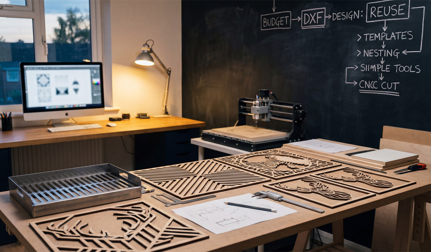
Running a profitable CNC business from a home workshop, like the one pictured above, isn't about having the largest industrial machine; it's about having the smartest workflow. If you look closely at the chalkboard on the wall, you will see a flowchart that reads: Budget -> DXF -> Design: Reuse -> Templates -> Nesting. This isn't just a scribble; it is the blueprint for scaling a hobby into a business. Today, we are going to break down how "Reusing" and "Nesting" your DXF files can double your output without doubling your work hours. The Power of "Design: Reuse" The chalkboard highlights a critical concept: Reuse. Many beginners make the mistake of designing every single project from scratch. This is a massive time-sink. Successful fabricators build a library of "Master Files." In the foreground of the photo, you can see several geometric deer head cutouts. Once you have a verified, high-quality DXF for a design like this, it becomes a permanent asset. You can cut it in plywood for a rustic look today, and cut the same file in brushed aluminum for a modern office next week. To start building your own library of reusable assets, check out our Full Access Bundle, which gives you thousands of designs ready to be your shop's "Master Files." Nesting: The Secret to Material Savings The diagram also points to "Nesting." Whether you are cutting the wooden geometric panels on the table or the metal tray on the left, material cost is your biggest expense. Nesting is the process of arranging your DXF parts as close together as possible on your material sheet to minimize waste. Good DXF files are clean and optimized, allowing your CAM software to nest them tightly without errors. If you are struggling with files that have "open loops" or won't nest correctly, you are throwing money in the scrap bin. Always start with optimized vectors to ensure you get the most out of every square inch of wood or steel. One Design, Multiple Applications This image perfectly illustrates the versatility of DXF files. On the workbench, we see: Geometric Wood Art: detailed, decorative designs perfect for Etsy stores or home decor markets. Metal Fabrication: A bent metal tray, showing that DXF files are also essential for functional, folded sheet metal parts. The beauty of the digital workflow is that the skills transfer seamlessly. If you can set up a toolpath for the wooden deer, you are halfway to cutting the metal tray. It all starts with the same file format. Streamline Your Shop Today You don't need a factory to produce factory-quality work. You just need a clean workspace, a reliable machine, and a strategy for managing your digital assets. If you are ready to test this workflow, download some of our Free DXF Files and practice the "Reuse and Nest" strategy shown on the chalkboard. For those turning this into a business, always ensure you are clear on the legal side of things by reviewing our License Agreement. Work smarter, minimize waste, and let your designs pay for themselves.
Precision Laser Cutting: Transforming Complex DXFs into Metal Art
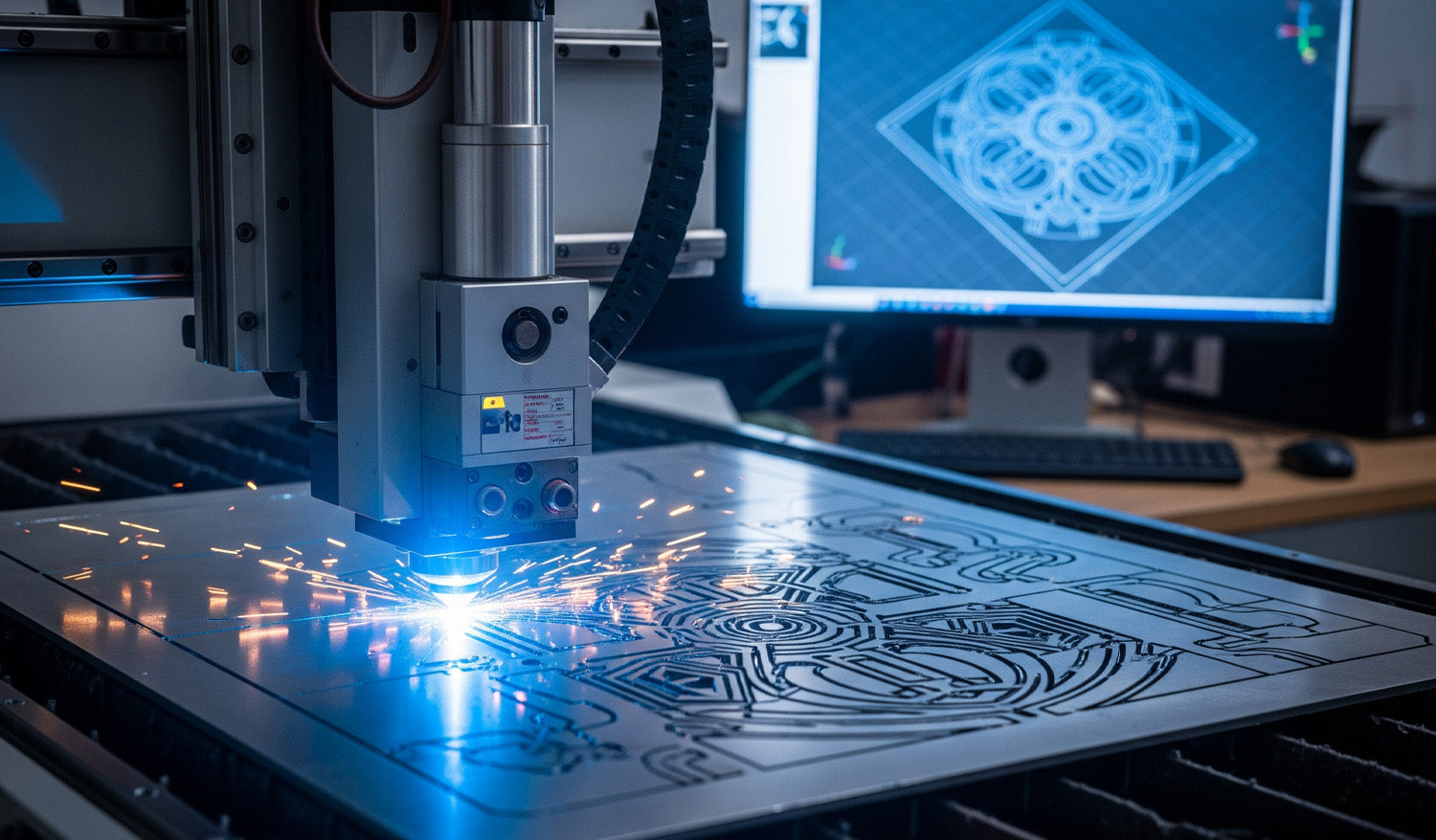
There is a specific thrill in watching a CNC laser machine execute a complex design. As the cutting head dances fast across the sheet metal, throwing sparks and leaving behind a perfectly crisp edge, you are witnessing the perfect synchronization of hardware and software. However, as shown in the image above, that beautiful physical cut—glimmering with sparks—is entirely dependent on the blue wireframe displayed on the monitor in the background. If your digital file is flawed, your machine will fail. In high-end metal fabrication, the line between a scrapped sheet of expensive steel and a profitable piece of art is drawn by the quality of your DXF file. The "Digital Twin" Concept Look at the relationship between the computer monitor and the cutting bed in the photo. The complex mandala design on the screen is the "Digital Twin" of the part being cut. For the machine to replicate that intricate geometry without error, the DXF file must be mathematically perfect. This means: Closed Loops: Every shape must be a continuous path. No Overlaps: Double lines confuse the laser, causing it to cut the same path twice, ruining the edge and overheating the material. Node Reduction: Too many nodes (data points) can cause the machine to "stutter," leading to jagged edges instead of smooth curves. To ensure your projects run this smoothly, we recommend starting with verified designs. You can test your machine’s calibration with our Free DXF Files before moving to larger sheets. Managing Heat and Deformation The sparks flying in the image represent intense heat. When cutting dense, intricate patterns like this geometric medallion, "Thermal Distortion" becomes a real risk. If your DXF file isn't optimized, the laser might cut too much detail in one small area at a time, warping the metal. Professional DXF files are designed to allow for proper spacing. Furthermore, inside your CAM software, you should utilize "cut path optimization" to spread the heat across the sheet. This ensures the piece stays flat and the dimensions remain accurate. Monetizing Complex Art Why go through the trouble of cutting such complex designs? Because that is where the profit lies. Simple squares and circles are easy, but intricate decorative panels, privacy screens, and custom wall art command high prices in the home decor market. The design shown in the photo is a prime example of a high-value item that can be sold for hundreds of dollars, despite low material costs. By investing in our Full Access Bundle, you gain instant access to a library of complex, high-margin designs that are ready to cut. We have done the hard work of designing so you can focus on the manufacturing and selling. Safety and Licensing As you scale up your production of these artistic pieces, remember that protecting your business is as important as protecting your eyes from the laser. Always ensure you have the right to sell the physical goods you produce. You can review our transparent License Agreement to cut with confidence. If you encounter issues with cut quality or software import errors, our FAQ Page is an excellent resource to troubleshoot common CNC problems. Keep your lens clean, your files cleaner, and let the sparks fly!
Precision Manufacturing: The Link Between Clean DXFs and Accurate Parts
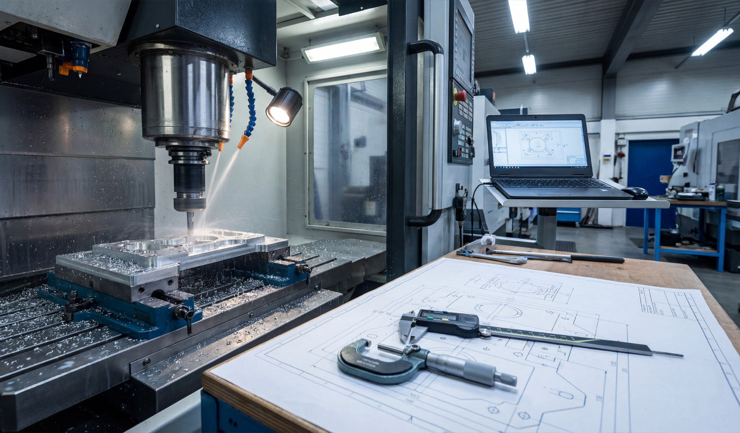
Precision in CNC machining is not an accident; it is the result of a rigorous alignment between your digital file and your physical machine. As captured in the photo above, the journey from a raw block of aluminum to a perfectly milled component involves three critical pillars: a clean CAD/CAM setup, precise physical verification using calipers and micrometers, and, most importantly, a flawless source file. Whether you are running a heavy-duty Vertical Machining Center (VMC) or a high-precision desktop router, the rule remains the same: the machine can only be as accurate as the DXF file you feed it. The Triangle of Precision: Examining the Workflow In the workshop image, you see the complete ecosystem required for high-tolerance manufacturing. Let's break down how these elements work together to create profitable parts: The Digital Twin (Laptop): The screen shows the 2D geometry (the DXF) being transformed into toolpaths. This is where errors usually start. If your DXF file has overlapping lines or unjoined vector nodes, your CAM software will generate erratic G-Code. The Physical Verification (Calipers & Blueprint): On the workbench, you see digital calipers and a micrometer sitting on top of a technical drawing. These tools are the judge and jury. They verify that what you downloaded matches what you cut. The Execution (CNC Mill): The machine in the background is removing material at high speed. There is no "undo" button here. This is why validating your files before hitting the green button is essential. Why DXF Files Matter for 2.5D Milling While many people associate DXF files strictly with 2D cutting (like plasma or laser), they are the backbone of projected 2.5D milling. When you are machining a bracket or a mechanical part, you import a DXF to define the pockets, contours, and drill locations. Using high-quality designs, such as those found in our Full Access Bundle, ensures that your geometry is mathematically perfect. A perfect circle in a DXF means a perfect bore on the machine. A segmented or low-resolution curve will result in "faceting" on your finished part, requiring hours of manual sanding and polishing to fix. From Prototype to Production The setup in the photo represents a "First Article Inspection." The operator is likely cutting the first piece to verify tolerances before running a full batch. To streamline this process in your own shop: Test with Free Files: Before committing to expensive material, run a test cut using one of our Free DXF Designs to calibrate your machine's backlash and kerf/tool offset settings. Check the Blueprint: Always compare the dimensions in your CAM software against your required specs. DXF files are unitless; ensure you aren't cutting millimeters as inches! Measure Twice: Use your calipers immediately after the roughing pass. If the dimensions are off, check if the issue is mechanical (tool wear) or digital (incorrect file scaling). Building a Business on Accuracy Customers pay for precision. Whether you are selling automotive parts or custom metal art, the ability to deliver exact replicas time and time again builds trust. By starting with professional-grade vector files, you eliminate the biggest variable in the equation. If you are unsure if your current software supports our file types, visit our FAQ Page. For those looking to sell the parts they manufacture, please review our License Agreement to understand your rights. Precision starts with the download.
Organizing Your CNC Business: Master Files, Backups, and Workflow
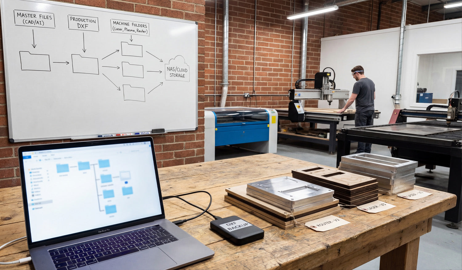
In a professional CNC workshop, the biggest silent killer of profit isn't dull tooling or power outages—it's disorganization. As illustrated in the photo above, establishing a rigid digital workflow is just as important as the physical machining itself. From the "Master Files" breakdown on the whiteboard to the physical "Version Tags" on the finished parts, we are going to explore how proper file management prevents costly mistakes, ensures you never overwrite a working design, and keeps your machines running while others are searching for missing files. The Whiteboard Strategy: Hierarchical File Structure If you look closely at the whiteboard in our workshop image, you will see a flowchart that separates the creative process from the manufacturing process. This is the difference between a hobbyist folder and a professional database. Master Files (CAD/AI): This is your "Source of Truth." These folders contain your original designs (Illustrator, Corel, Fusion 360). You never cut directly from these files. Production DXF: These are your clean, exported vectors. They have been scaled, the nodes have been optimized, and they are ready for CAM. Building a library of reliable DXFs is essential. You can jumpstart this library with our Full Access Bundle, giving you thousands of organized, production-ready files. Machine Folders: Notice the split on the board for "Laser," "Plasma," and "Router." A file optimized for the kerf of a plasma cutter might not work for a fine-detail laser engraving. Separate your G-Code and DXFs by machine type to avoid running the wrong file on the wrong equipment. The Hardware: Backups and Redundancy On the workbench, you can see a laptop managing the file explorer alongside an external drive labeled "DXF BACKUP." This small device is your insurance policy. CNC businesses run on digital assets. If your main computer crashes or falls victim to ransomware, you could lose years of design work. The whiteboard also points to "NAS / Cloud Storage." Hybrid storage is the modern standard. Use a local drive (SSD) for fast access during production, but ensure your "Master Files" are synced to the cloud. This allows you to download your files from anywhere, ensuring you can grab a design from our Free DXF Collection at home and have it waiting at the shop when you arrive. The Physical Link: Version Control Tags Perhaps the most subtle but important detail in the photo is the stack of cut parts labeled "Router - V2" and "Laser - V1." Digital organization must translate to physical tracking. When prototyping a new product, always tag your physical prototypes with the file version used to cut them. There is nothing worse than achieving the perfect cut, mixing up the parts, and then not knowing which version of the DXF file created that perfect fit. If you are struggling with file versions or compatibility, check our Frequently Asked Questions for guidance on standardizing your formats. Conclusion: Organized Data Equals Faster Production Organization doesn't slow you down; it speeds you up. By implementing the "Master to Machine" workflow shown in the image, you reduce the time between a customer order and a finished part. If you have questions about licensing for your organized library, be sure to review our License Agreement before scaling up your production.
From Screen to Sparks: The Ultimate CNC Workflow Guide
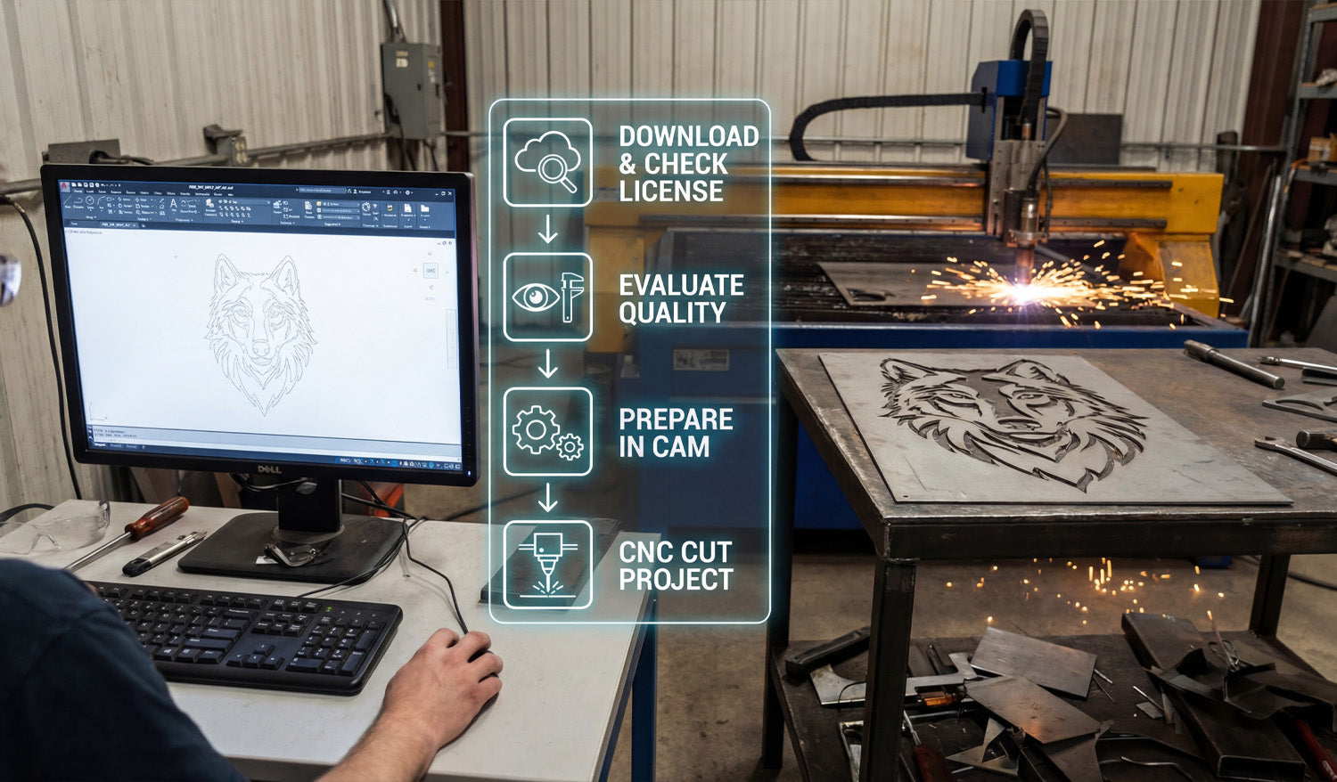
Bridging the gap between a digital design on a computer screen and a hot, finished metal part on a plasma table is the most critical skill for any fabricator. As illustrated in the workflow overlay of our latest workshop photo, the journey involves more than just pressing "print." It requires a disciplined four-step process: sourcing the right file, verifying its quality, preparing the toolpaths in CAM, and finally, executing the cut. Mastering this specific workflow is what turns a garage hobbyist into a profitable commercial shop, ensuring that the wolf design you see on the screen matches the precision cut on the table. Step 1: Download & Check License The process begins long before the sparks fly. It starts with sourcing high-quality vector files. Whether you are downloading from our Free DXF Collection or purchasing premium bundles, the very first step is understanding your usage rights. As seen in the first icon of the workflow, you must "Check License." Are you cutting this wolf for a personal project, or are you planning to sell 50 units at a local craft fair? Always review the Legal Usage License Agreement to ensure your commercial production is fully authorized. Step 2 & 3: Evaluate Quality and Prepare in CAM Once the file is downloaded, don't rush to the machine. As the second and third icons suggest, you must Evaluate Quality and Prepare in CAM. Open the file in your CAD software (like AutoCAD or Fusion 360, shown on the monitor). Check for open loops, double lines, or excessive nodes that can cause your machine to stutter. Next, move to your CAM software to generate the G-Code. This is where you define your lead-ins and lead-outs—essential for plasma cutting to avoid burn marks on the finished edge of detailed designs like the wolf's fur. If you are new to this and unsure about file compatibility, our FAQ page handles common questions regarding file types and software setup. Step 4: The Cut & The Profit Finally, we reach the stage shown on the right side of the image: CNC Cut Project. This is where the preparation pays off. A clean DXF file results in a smooth cut with minimal dross, reducing the time you spend grinding and finishing the metal later. Designs like this geometric wolf are high-value items in the home decor market. By accessing our Full Access Bundle, you ensure a steady stream of "cut-ready" designs. This allows you to focus on production and sales rather than spending hours fixing broken vectors. Ready to Spark Your Production? Consistency is key. By following this standardized workflow—Download, Check, Prepare, Cut—you minimize wasted material and maximize production speed. If you have any specific questions about getting started or need support with a file, feel free to contact us directly. It’s time to turn that digital potential into steel reality.
The Universal CNC Workflow: Using One DXF for Wood and Metal
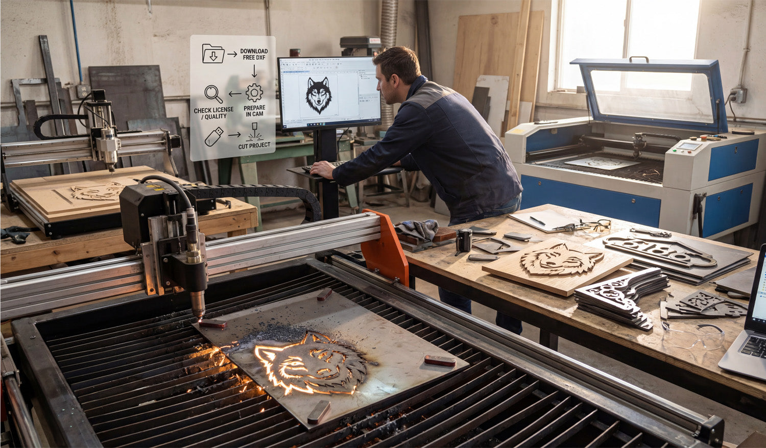
Success in a modern CNC workshop isn't just about owning the most expensive machinery; it is about establishing a seamless workflow that turns digital concepts into physical profit. As seen in the image above, a single high-quality DXF design can be the foundation for multiple product lines, whether you are carving intricate wood art on a router or slicing through heavy-gauge steel with a plasma cutter. Understanding the journey from clicking "download" to watching the sparks fly is what separates hobbyists from professional fabricators. The 4-Step Profit Workflow If you look at the overlay in our workshop photo, you will see a simplified roadmap that every successful shop follows. Let's break down these critical steps: 1. Download Free DXF: It all starts with the file. You don't always need to design from scratch. Using resources like our Free DXF Files allows you to test new ideas without the upfront time investment of CAD drawing. 2. Check License / Quality: This is the step most beginners skip, but professionals never do. Before you cut, ensure the nodes are clean (no open loops) and that you have the legal right to sell the finished product. You can review our Legal Usage License Agreement to understand exactly how you can monetize our designs. 3. Prepare in CAM: Whether you use SheetCam, VCarve, or Fusion 360, this is where you apply your toolpaths. The wolf design in the photo requires different settings for the wood router (left) compared to the plasma table (front). 4. Cut Project: The final step is execution. With a verified, clean DXF file, your machine can focus on what it does best—cutting precision parts. One Design, Infinite Materials The beauty of vector art is its versatility. In the photo, notice how the same "Wolf Head" design is being processed in two completely different ways. On the left, a CNC Router is milling the design into wood, creating a warm, rustic piece perfect for home interior decor. In the foreground, a plasma cutter is blasting through a steel sheet to create a durable, industrial piece suitable for outdoor gates or garden art. By using a diverse library, such as our Full Access Bundle, you can offer your customers the same design in various finishes—wood, acrylic, stainless steel, or mild steel—without doing any extra design work. From Scrap to Sales Look at the workbench on the right side of the image. You see finished products like the "8186" address sign and decorative brackets. These items represent the bread and butter of many CNC businesses. A small sheet of metal often costs very little, but once you apply a custom address via a DXF cut, its value skyrockets. To keep your business efficient, always keep your laptop close to the production area (as shown on the right). Being able to quickly access your file library and make minor adjustments to scale or nesting can save you hours of downtime. Need Help Getting Started? If you are unsure about which files work best for your specific machine, or if you are running into compatibility issues with your CAM software, check out our Frequently Asked Questions. We are here to help you turn those digital lines into solid revenue.
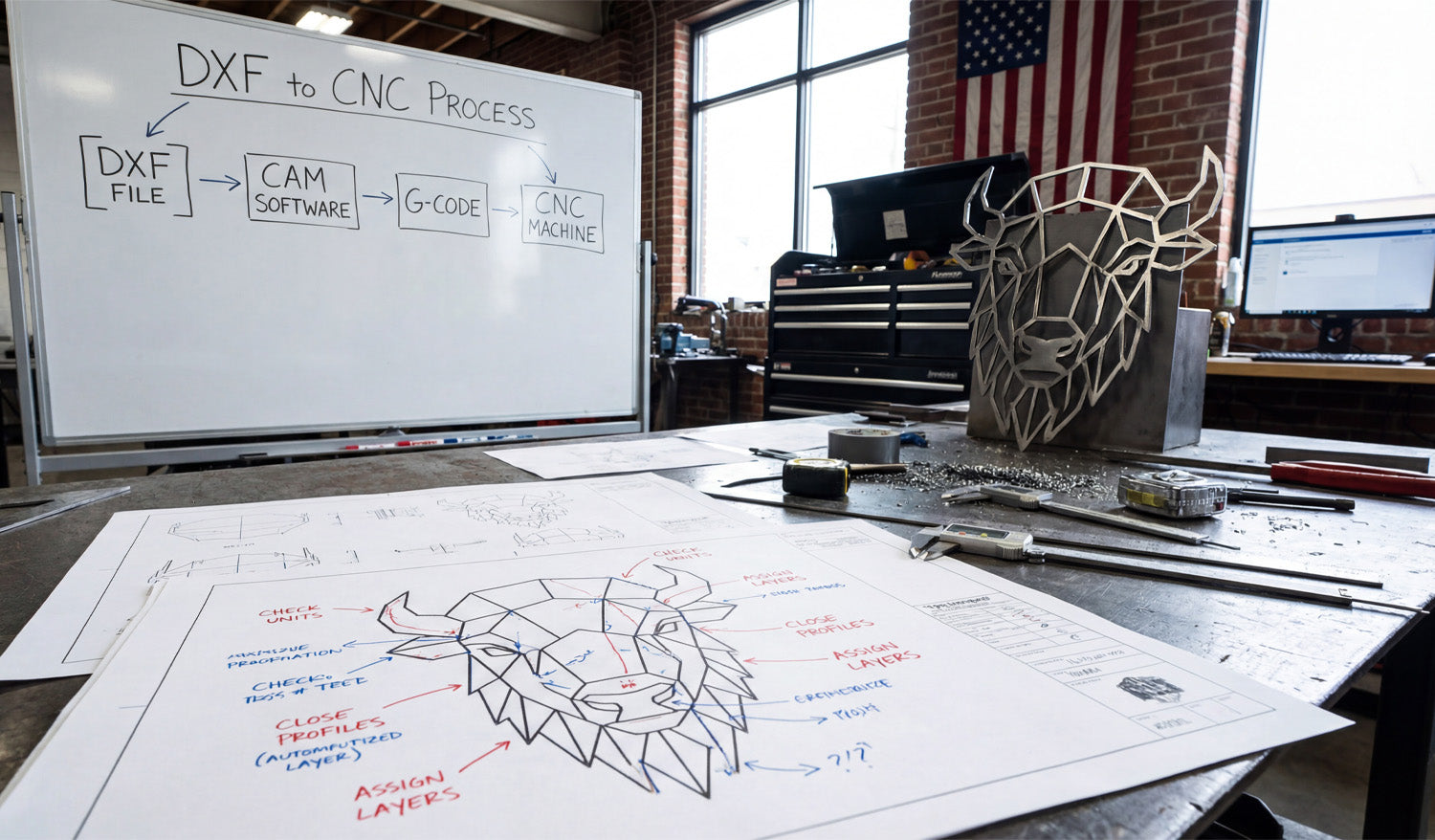
From Screen to Steel: Mastering the DXF to CNC Process
Creating a stunning piece of metal art, like the geometric bison head standing proudly on the workbench in our latest photo, doesn't start with the spark of a plasma torch or the spin of a router bit. It starts long before that, with a clean digital file and a solid understanding of the workflow. Many beginners get intimidated by the technical jargon, but as the whiteboard in our shop demonstrates, the path from a digital concept to a physical object is actually a logical, four-step journey. Whether you are running a hobbyist garage shop or a commercial fabrication business, mastering the transition from a DXF file to a finished product is the single most important skill you can learn to turn raw material into profit. The 4-Step Workflow: Decoding the Whiteboard If you look at the whiteboard in the background of our workshop image, you will see the holy grail of CNC machining simplified into four boxes. Let’s break down exactly what this "DXF to CNC Process" means for you. 1. DXF File: This is your blueprint. It is a 2D vector drawing that defines the geometry of your part. Without a clean DXF, nothing else matters. This is where DXF Files for CNC comes in, providing you with ready-to-cut designs. 2. CAM Software: Computer-Aided Manufacturing (CAM) software is the bridge. You import your DXF here to define your "toolpaths." This is where you tell the computer, "Cut on the outside of this line" or "Engrave clearly on this line." 3. G-Code: Your CAM software translates those toolpaths into G-Code—a language of coordinates (X, Y, Z axis) that your specific machine understands. 4. CNC Machine: Finally, the machine reads the G-Code and executes the cuts, turning your metal sheet into the geometric bison you see on the table. The Secret is in the Blueprint: Optimization Tips Look closely at the technical drawing (blueprint) on the workbench. You will see handwritten red and blue notes pointing to specific parts of the bison design. These aren't just doodles; they illustrate the critical rules of DXF File Optimization that prevent failed cuts. "Close Profiles" You see the note pointing to the bison's ear that says "Close Profiles"? This is vital. If a shape in your design isn't fully closed (meaning the start point and end point touch), the CNC machine doesn't know where the shape ends. This often results in the software treating the line as a simple slit rather than a cut-out shape. Always ensure your vectors are joined. "Check Units" Another note emphasizes checking your units. DXF files are unitless by nature, but your CAM software isn't. If you import a design drawn in millimeters into a fast-paced environment set to inches, you might end up with a microscopic bison or a design that’s larger than your machine bed. Always verify your scale before generating G-Code. "Assign Layers" The note "Assign Layers" suggests separating your cutting operations. For complex art, you might want to engrave certain details (like the texture on the bison) before you cut the outer profile. Assigning these to different layers in your DXF file makes setting up your CAM operations much faster. From Sheet Metal to Profit The finished bison head in the photo isn't just a decoration; it's a product. Geometric animal heads are currently a massive trend in interior design and office decor. By utilizing our Full Access Bundle, you gain access to thousands of designs just like this one. Imagine the ROI: A sheet of mild steel is relatively affordable. However, once you cut it, clean it, and perhaps powder coat it, that piece of steel increases in value by 10x or 20x. This is the power of CNC and digital design—you are selling artistry and precision, not just metal. Start Your Project Today You don't need to be an engineer to understand this process. You just need high-quality files and the willingness to learn. If you are new to this, we recommend downloading some of our Free DXF Designs to practice the workflow shown on the whiteboard. Remember to check our License Agreement if you plan to sell the physical items you create. If you have questions about file types or compatibility, our FAQ page is a great resource to get you unstuck. Every master craftsman started with a single file. Grab yours and start cutting.
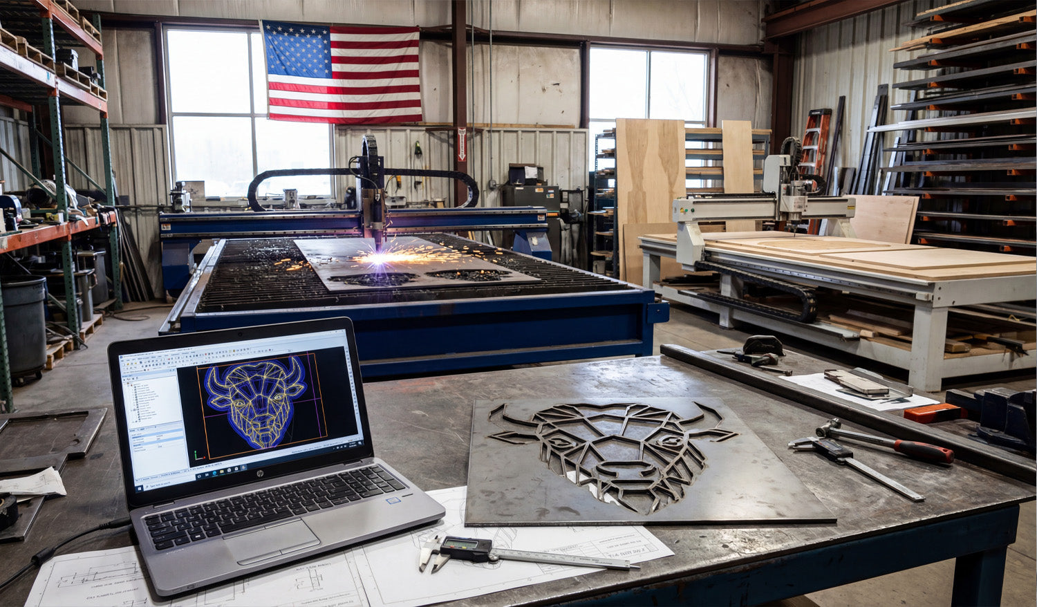
Geometric Bull Wall Art DXF File for CNC Plasma & Laser
Turning a digital concept into a tangible, high-value product is the ultimate goal of every CNC shop. As seen in the image above, the journey starts on a laptop screen with a precise vector design—in this case, a geometric bull head—and ends on the workbench as a cleanly cut steel masterpiece. Whether you are running a plasma table in an industrial warehouse or a smaller setup in your garage, mastering the workflow from DXF file to finished metal art is the key to unlocking new revenue streams in the booming home decor market. The Rise of Geometric Metal Art If you look closely at the laptop screen in the photo, you will see a "low poly" or geometric design style. This isn't just an artistic choice; it is a strategic business move. Modern interior designers love this style because it fits both rustic and contemporary homes. For a CNC business owner, these designs are gold because: They Cut Fast: Straight lines and defined angles are easier for plasma and laser cutters to process than complex organic curves. High Perceived Value: A simple sheet of mild steel transforms into "modern art" the moment it is cut. Scalability: You can cut this bull head 12 inches wide for a wall hanging, or 4 feet wide for a commercial sign, using the same Full Access Bundle of files. Technical Breakdown: From Screen to Spark The transition from the blue lines on the computer to the steel plate on the table requires attention to detail. Notice the calipers on the workbench? Precision counts. 1. Optimizing the DXF In the CAD software shown on the laptop, the design looks perfect. But for the plasma torch in the background to cut it cleanly, the file needs to be "machine-ready." This means ensuring there are no open contours and that the spacing between the geometric lines is wide enough to handle the thermal distortion of the metal. If the lines are too close, the heat from the plasma arc might melt the thin web of material between them. 2. Managing Lead-ins and Lead-outs For a piece like this geometric bull, where aesthetics are everything, you cannot have pierce marks ruining the visual flow. In your CAM software, you must place your lead-ins (where the torch starts) and lead-outs inside the "scrap" parts of the design, not on the finished edge. This ensures the outer contour remains crisp and clean, requiring less grinding later. Diversifying Your Shop Capabilities The background of this workshop tells another success story. While the plasma table handles the steel bull, there is a CNC Router to the right working on wood. This is the definition of a resilient business. You can use the exact same DXF file of the geometric bull to carve a wooden version on your router or engrave it onto slate. If you are looking to expand your library to feed multiple machines, check out our complete collection of designs. Start Your Project You don't need to be a CAD wizard to produce professional results like the one in the photo. We have done the design work for you. You can test your machine's capabilities right now by downloading some of our Free DXF Files. If you have any trouble with file scaling or import settings, our team is here to help. Visit our Contact page or email us at info@dxffilesforcnc.com.
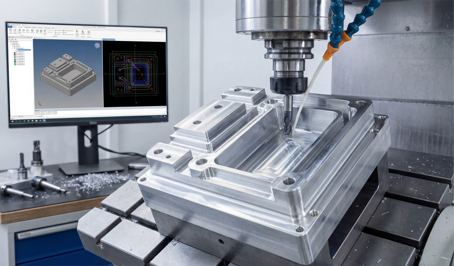
Precision CNC Milling: Transforming DXF Files into 3D Parts
High-precision CNC machining is the bridge between digital creativity and physical reality. This article explores how CAD/CAM software translates 2D DXF data into complex 3.5-axis toolpaths, turning a simple digital sketch into a robust metal component. We discuss the importance of clean vector files for milling operations and how to optimize your workflow from the computer screen to the workshop floor. From CAD Monitor to Metal Chips: The Milling Workflow Look at the photo above. It perfectly captures the "brain" and the "brawn" of modern manufacturing. On the left, a monitor displays a complex CAD/CAM simulation with multi-colored toolpaths. On the right, a vertical machining center (VMC) is executing those instructions, cutting into a block of metal with cooling fluid streaming down. As a CNC expert, I often hear people say, "DXF files are just for plasma or laser cutters." This image proves that is a misconception. While DXF files are 2D, they are often the foundational "skeleton" for the 3D parts you see being milled here. The Secret of 2.5D Machining The part being machined in the photo has pockets, raised islands, and drilled holes. Believe it or not, the geometry for these features likely started as a 2D DXF file. This process is called 2.5D Machining. Pocketing: You import a closed DXF shape (like a rectangle or circle) into your CAM software. You then tell the machine, "Clear out everything inside this line to a depth of 1 inch." Profiling: You select the outer contour from the DXF and tell the machine, "Cut along the outside of this line to cut the part loose." Drilling: The circles in a DXF file act as precise center points for drill bits and taps. If you are looking to practice these operations, you can grab some of our Free DXF Files to test your CAM software's pocketing and profiling strategies. Why Clean Data Matters for Milling In the image, notice the precision of the simulation on the screen. The red, blue, and green lines represent the exact path the tool will take. If your source file has gaps, overlapping lines, or "noise," that beautiful simulation turns into a machine crash. For milling, file optimization is even more critical than for laser cutting. A laser might just leave a bad edge; a milling machine hitting a bad vector can break a $200 carbide end mill. That is why we ensure every design in our Full Access Bundle is free of open contours and stray nodes. We do the digital cleanup so you can focus on the machining parameters. Expanding Your Market If you own a mill like the one pictured, you aren't limited to making machine parts. You can use artistic DXF designs to mill engravings into aluminum valve covers, create custom brass stamps, or machine intricate molds. The connection between the software on the left and the spindle on the right is only as good as the file you feed it. Whether you are running a high-end industrial mill or a desktop CNC router, starting with professional-grade vector files is the key to efficiency. Have questions about converting 2D files for 3D machining applications? Visit our FAQ page or contact our technical team at info@dxffilesforcnc.com.

