High-precision CNC machining is the bridge between digital creativity and physical reality. This article explores how CAD/CAM software translates 2D DXF data into complex 3.5-axis toolpaths, turning a simple digital sketch into a robust metal component. We discuss the importance of clean vector files for milling operations and how to optimize your workflow from the computer screen to the workshop floor.
From CAD Monitor to Metal Chips: The Milling Workflow
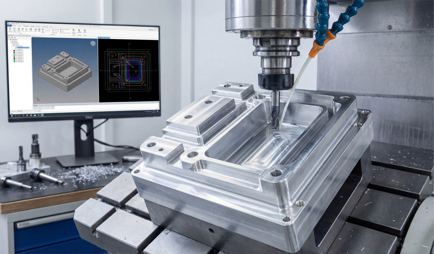
Look at the photo above. It perfectly captures the "brain" and the "brawn" of modern manufacturing. On the left, a monitor displays a complex CAD/CAM simulation with multi-colored toolpaths. On the right, a vertical machining center (VMC) is executing those instructions, cutting into a block of metal with cooling fluid streaming down.
As a CNC expert, I often hear people say, "DXF files are just for plasma or laser cutters." This image proves that is a misconception. While DXF files are 2D, they are often the foundational "skeleton" for the 3D parts you see being milled here.
The Secret of 2.5D Machining
The part being machined in the photo has pockets, raised islands, and drilled holes. Believe it or not, the geometry for these features likely started as a 2D DXF file. This process is called 2.5D Machining.
- Pocketing: You import a closed DXF shape (like a rectangle or circle) into your CAM software. You then tell the machine, "Clear out everything inside this line to a depth of 1 inch."
- Profiling: You select the outer contour from the DXF and tell the machine, "Cut along the outside of this line to cut the part loose."
- Drilling: The circles in a DXF file act as precise center points for drill bits and taps.
If you are looking to practice these operations, you can grab some of our Free DXF Files to test your CAM software's pocketing and profiling strategies.
Why Clean Data Matters for Milling
In the image, notice the precision of the simulation on the screen. The red, blue, and green lines represent the exact path the tool will take. If your source file has gaps, overlapping lines, or "noise," that beautiful simulation turns into a machine crash.
For milling, file optimization is even more critical than for laser cutting. A laser might just leave a bad edge; a milling machine hitting a bad vector can break a $200 carbide end mill. That is why we ensure every design in our Full Access Bundle is free of open contours and stray nodes. We do the digital cleanup so you can focus on the machining parameters.
Expanding Your Market
If you own a mill like the one pictured, you aren't limited to making machine parts. You can use artistic DXF designs to mill engravings into aluminum valve covers, create custom brass stamps, or machine intricate molds.
The connection between the software on the left and the spindle on the right is only as good as the file you feed it. Whether you are running a high-end industrial mill or a desktop CNC router, starting with professional-grade vector files is the key to efficiency.
Have questions about converting 2D files for 3D machining applications? Visit our FAQ page or contact our technical team at info@dxffilesforcnc.com.


