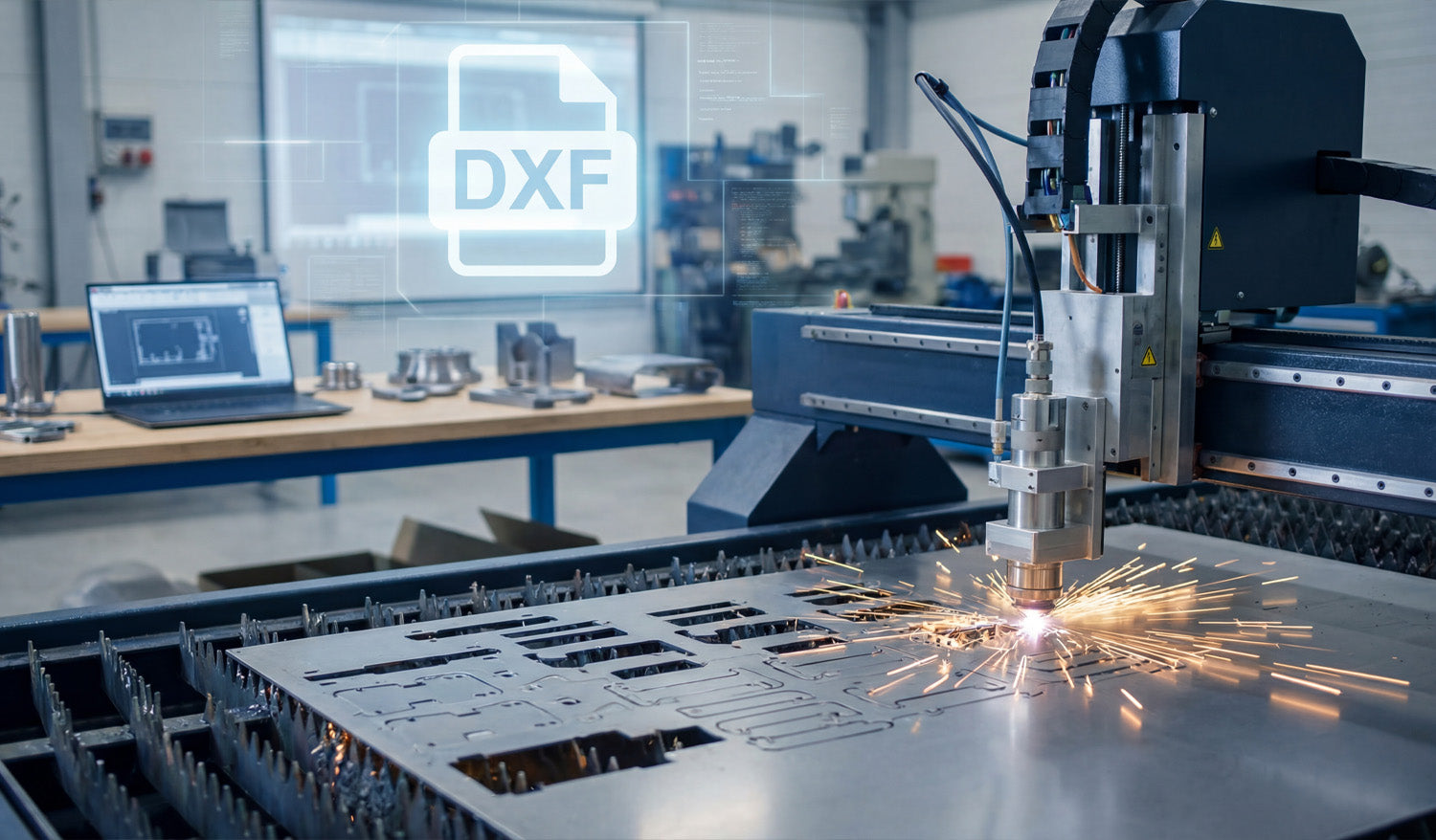
CNC & DXF Design Guides
CNC & DXF Design Guides
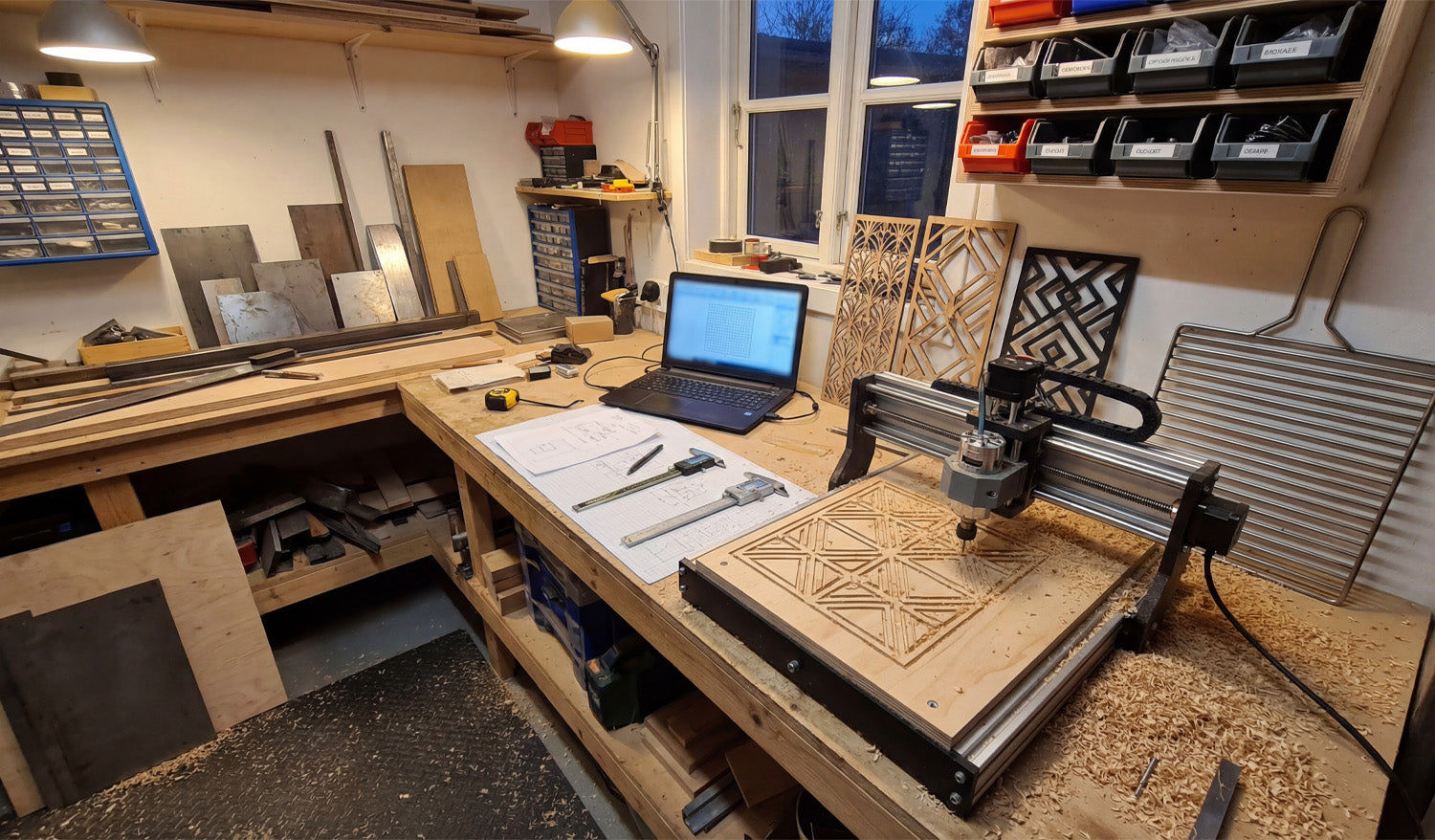
How to Design DXF Files for CNC Cutting on a Budget
Designing DXF files for CNC cutting on a budget is not about “cutting corners”—it is about using the right free or low-cost tools, smart design habits, and efficient workflows so you waste less time, material, and machine runtime. Why Good DXF Design Saves You Money Every mistake in a DXF file has a price: scrap material, broken tools, re-cuts, or hours spent fixing geometry. When you design with cost in mind, you: Reduce trial-and-error on the CNC machine. Cut fewer test pieces before production. Spend less money on software and more on actual projects. Reuse proven designs instead of starting from zero each time. A “budget-conscious” DXF workflow is really a “time-and-material conscious” workflow. 1. Choose Budget-Friendly Software for DXF Design You do not need expensive CAD licenses to create solid DXF files. Many hobbyists and small shops start with: Free 2D CAD tools: Simple line, arc, and polyline tools are enough for a lot of CNC work. Free or low-cost vector editors: Great for signs, wall art, and decorative designs that export to DXF. Entry-level CAD/CAM packages: Some offer personal or hobby licenses with DXF import/export built in. Pick one tool and learn it deeply instead of jumping between five different programs. Familiarity is a huge cost saver. 2. Start from Templates Instead of Redesigning Everything Drawing from scratch for every project is expensive in time. Templates turn one good design into many budget-friendly variations. Create base templates for common shapes such as brackets, gussets, plaques, or sign blanks. Save “ready-to-go” text layouts you can quickly swap names or numbers into. Build standard hole patterns and slot sizes that you reuse across projects. Each template is like a small tool in your digital toolbox. You invest once and benefit over and over again. 3. Design with Material and Sheet Size in Mind One of the easiest ways to waste money is to ignore stock sizes while designing. Budget-first DXF files are drawn for real sheets. Know your common sheet sizes (for example, 4×8 ft, 4×4 ft, or standard plywood/metal plates). Design parts so they nest efficiently on those sheets. Avoid odd overall dimensions that leave large unusable offcuts. Even a simple change—like adjusting a panel from 1010 mm wide to 1000 mm—can make nesting easier and reduce material waste. 4. Keep Geometry Simple and Machine-Friendly Complex designs are not just harder to cut—they also cost more in machine time and post-processing. Simple is budget-friendly. Use clean contours with fewer nodes instead of “noisy” traced artwork. Remove micro details that will never show up in wood or metal at real scale. Avoid tiny islands and razor-thin bridges that break during cutting or cleaning. Replace jagged curves with smooth arcs where possible. Smoother toolpaths cut faster, wear tools less, and need less cleanup—all of which put money back in your pocket. 5. Reuse Design Elements Across Multiple Projects Once you have invested time designing a good DXF element, do not let it live in just one project. Build a small DXF library of icons, borders, ornaments, and commonly used parts. Copy and adapt these elements into new designs instead of redrawing them. Combine multiple existing pieces to create new “hybrid” designs with minimal effort. This strategy dramatically reduces design time for each new product, especially if you sell CNC-cut items online or locally. 6. Design for Easy Fixturing and Assembly Budget design is not just about cutting—it is also about how quickly you can assemble and finish parts. Add alignment holes or tabs so pieces self-locate during assembly. Use slotted joints that can be dry-fit before committing to fasteners or glue. Round sharp internal corners so parts slide together without filing. Make sure you can clamp or screw parts easily during gluing or welding. When parts fit together easily, you spend less time reworking and more time finishing or shipping projects. 7. Match Detail Level to Machine Type and Bit Size Designing tiny detail your machine cannot reproduce is a direct waste of time and money. On small lasers, you can keep fine detail, but still avoid bridges thinner than your kerf. On routers, do not design internal gaps smaller than your cutter diameter. On plasma tables, use bold shapes and avoid micro features that will blow out or warp. Before spending time polishing a DXF, ask: “Will my machine and material actually show this detail?” If not, simplify. 8. Use Layers to Organize Operations in One DXF Well-layered DXF files reduce confusion and programming time—especially when you are working alone and wearing every hat. Create layers such as OUTER_CUT, INNER_CUT, ENGRAVE, and REFERENCE. Keep dimensions and centerlines separate so they are not accidentally cut. Use colors or line types that your CAM software can map to different tools or settings. Less time spent sorting geometry in CAM means more time running the machine—or relaxing. 9. Test on Scrap and Lock In “Production-Ready” DXF Files On a tight budget, you cannot afford to scrap full sheets. Use small tests to dial in your DXF designs and settings. Cut a small section of a complex pattern before running the whole panel. Test one joint, slot, or tab for fit before cutting the full set. Once a design is proven, save a copy as _PROD or _FINAL and do not edit it casually. This creates a small library of “known good” DXF files you can reuse without re-testing every time. 10. Organize Your DXF Library to Avoid Rework Time is money, especially in small shops and one-person operations. A messy file system forces you to redesign parts you already made. Store designs in folders by category (signs, brackets, jigs, decor, etc.). Use file names that include size, material, and version (for example, tree_panel_600mm_plywood_v2.dxf). Keep a simple list or spreadsheet of your best-selling or most-used DXF designs. The less time you spend digging for a file, the more time you can spend cutting and finishing real parts. Bonus: Know When to Buy Instead of Design Designing everything yourself sounds cheap, but sometimes buying a done-for-you DXF is actually the budget move. If a design would take you hours to draw, compare that to the price of a ready-made file. Look for bundles that give you hundreds or thousands of designs for less than one hour of your shop rate. Use purchased designs as a base and tweak them for your own style, sizes, or customers. Mixing your own custom work with high-quality purchased DXF files is often the fastest way to build a profitable product range on a budget. Conclusion Designing DXF files for CNC cutting on a budget does not mean settling for low quality—it means using smart tools, reusable templates, material-aware layouts, and machine-friendly geometry. When you keep an eye on time, material, and complexity at the design stage, your CNC projects become cheaper to run, easier to repeat, and much more sustainable for a small shop or home workshop.

CNC for Hobbyists: How to Use DXF Files for Personal Projects
CNC for hobbyists becomes a lot more fun and a lot less frustrating when you understand how to use DXF files for your personal projects—whether you are making wall art, workshop jigs, cosplay props, or custom gifts. What Is a DXF File and Why Should Hobbyists Care? DXF (Drawing Exchange Format) is a vector file type that stores shapes as lines, arcs, and curves instead of pixels. For a hobby CNC user, this means: Clean shapes: Your CNC follows exact paths instead of “fuzzy” edges from images. Easy scaling: You can resize designs without losing quality. Wide compatibility: Most CAD, CAM, and CNC programs can import DXF files directly. If you have ever tried to cut from a JPG and ended up with messy toolpaths, switching to DXF will feel like a big upgrade. Typical DXF-Based Projects for CNC Hobbyists DXF files are perfect for many personal CNC projects, including: Decorative wall art and signs in wood, metal, or acrylic. Workshop jigs, templates, and measuring tools. Custom name plates, key holders, and door signs. Cosplay and prop parts cut from foam, MDF, or plastic. Layered 3D panels and inlays for furniture or decor. Instead of drawing everything from scratch, you can start from ready-made DXF designs and adapt them to your own style. Step 1: Choose the Right CNC Machine and Material Before you download or design any DXF, think about what you are cutting with and what you are cutting into. Laser cutters: Great for thin wood, MDF, acrylic, and light engraving. CNC routers: Ideal for plywood, solid wood, plastics, and soft metals (with the right setup). Small plasma tables: Good for hobby metal art and brackets, but with a wider kerf than lasers. Once you know your machine and typical material thickness, you can pick DXF designs that match what your setup can realistically handle. Step 2: Find or Download DXF Files for Personal Use You do not need to be a CAD expert to enjoy CNC. There are many ready-to-use DXF designs made for hobbyists. Look for: Free sample files: Many sites (including ours) offer free DXF files you can try on your machine. Project-based bundles: Collections focused on wall art, animals, signs, or workshop tools. License clarity: Check whether a file is allowed for personal use only or also for selling finished products. Starting with proven DXF files lets you test your machine and settings before you move on to your own custom designs. Step 3: Open DXF Files in Your CAD or CAM Software Once you have a DXF file, the next step is to bring it into software that connects to your CNC. Import the DXF into your CAM program or CAD/CAM combo software. Check the scale and units (millimeters or inches) and measure one known dimension. Make sure all shapes are closed paths with no gaps or duplicated lines. Separate cut lines and engraving lines onto different layers or colors if your software supports it. This quick check prevents surprises like oversized parts or incomplete cuts when you start the job. Step 4: Resize and Customize DXF Files for Your Project One of the best parts of DXF-based projects is how easy it is to customize them for your space or ideas. Scale up or down: Adjust the overall size to fit your material and project area. Add holes or slots: Include mounting holes, hooks, or screw points for hanging and assembly. Edit text: Replace generic words with names, dates, or quotes. Combine designs: Merge two or more DXF files into one unique layout. Just remember that if you scale a design too small, very thin details might become too weak to cut cleanly. Step 5: Match Detail Level to Your Hobby CNC Setup Not every hobby machine can cut ultra-fine detail, and that is okay. The key is to match design complexity to your tool. For small lasers, you can keep more detail in thin plywood or acrylic, but still avoid hairline bridges. For desktop routers, make sure narrow gaps are wider than your bit diameter. For hobby plasma, use bold shapes and thicker webs so parts stay strong. If a DXF looks extremely detailed on screen, consider simplifying it a bit before cutting on a small or entry-level machine. Step 6: Set Up Toolpaths and Cutting Parameters With the DXF imported and adjusted, it is time to tell your machine how to move. Assign inside cuts for holes and internal shapes, and outside cuts for outer profiles. Select feed rates, speeds, power, and depth based on your material and tool. Add tabs if necessary so small parts do not shift or fall out during cutting. Simulate the job in your CAM software to confirm the order and direction of cuts. Even as a hobbyist, taking a moment to simulate toolpaths can save material and frustration. Step 7: Run Test Cuts and Keep Notes Your first cut with a new DXF is a learning experience. Treat it like a test run, not a failure if something needs adjustment. Use scrap material or cut a smaller version of the design first. Note which settings produced clean edges and good fits. Adjust scaling, kerf compensation, or feed rates if holes are tight or edges look rough. Write your best settings on a label, in a notebook, or in a digital log for next time. Over time, your personal notes become a hobby “playbook” that makes future projects much easier. Safety and Practical Tips for Hobby CNC Users Even for personal projects in a garage or small workshop, safety and basic practice still matter. Wear eye protection and follow your machine’s safety guidelines. Use proper dust collection or ventilation when cutting wood, plastics, or metals. Secure your material firmly to avoid shifting or tipping during cuts. Stay nearby while the machine is running, especially on new designs. A careful approach keeps CNC as an enjoyable hobby instead of a stressful one. Ideas to Grow Your CNC Hobby with DXF Files Once you are comfortable using DXF files, you can: Build a small library of favorite designs that you reuse for gifts and personal decor. Experiment with layered projects using multiple DXF shapes stacked at different depths. Create custom fixtures and jigs that make your other DIY projects easier. Slowly move toward selling finished pieces locally or online, if the license on your DXF files allows it. The more you practice, the more your CNC hobby turns into a powerful creative tool for both fun and potentially side income. Conclusion For hobbyists, DXF files are the key to unlocking the full potential of small CNC machines. They let you start from clean, accurate designs, customize them to fit your ideas, and run them confidently on lasers, routers, or plasma tables. With a simple workflow—find a DXF, clean it, customize it, test it—you can turn personal project ideas into real, physical pieces that look professional even in a home workshop.
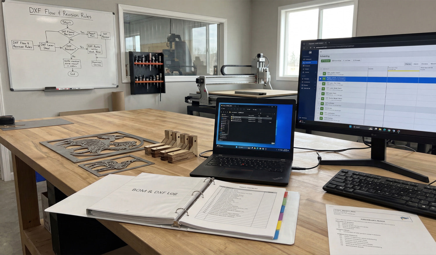
How to Manage Multiple DXF Files for Large-Scale CNC Projects
Managing multiple DXF files for large-scale CNC projects is all about control: clear structure, consistent naming, and a simple system that keeps designers, programmers, and machine operators working from the same, correct files every time. Why Large-Scale CNC Projects Need a DXF System (Not Just Folders) Cutting one small sign is easy. Cutting hundreds of parts for a big install, production run, or full product line is different. You may have: Dozens or hundreds of DXF files for a single project. Multiple machines (laser, plasma, router) using different versions of the same part. Revisions, client changes, and engineering updates happening mid-job. Without a system, DXF files get duplicated, lost, or mixed up. A simple structure and workflow lets you scale up without chaos. 1. Organize DXF Files by Project First, Then by Machine For large jobs, think in terms of projects, not just part types. A solid starting structure looks like this: Projects Project_ABC_2025 00_Input (customer drawings, PDFs, photos) 10_CAD_Master (original CAD and vector files) 20_DXF_Production Laser Plasma Router 30_CAM (CAM project files and nesting layouts) 40_GCode (posted NC programs) 99_Docs (BOM, notes, approvals) This structure keeps everything for one project in one place, while still separating DXF files by machine type. 2. Use a Naming Convention That Scales When you have many DXF files, good names are more useful than good memory. A simple, scalable pattern might be: [ProjectCode]_[PartID]_[Material]_[Thickness]_[Process]_[Rev].dxf For example: ABC01_PanelA_steel_3mm_laser_R1.dxf ABC01_Bracket02_aluminum_5mm_plasma_R2.dxf Key points: ProjectCode: Links the part to a specific job or customer. PartID: Matches your drawing number or BOM code. Material & thickness: Makes it easy to pick the right file for the right sheet. Process: Laser, plasma, router, waterjet, etc. Revision: R1, R2, R3… so you always know which is latest. 3. Separate Master Design Files from Production DXF Files In large projects, master design files and production DXF files should never be the same thing. Master files: CAD, AI, SVG, or parametric models with full design detail. Production DXF: Clean 2D profiles ready to import into CAM or the controller. Keep master files in 10_CAD_Master and export only the geometry you actually need into 20_DXF_Production. This way: Design changes are made in the master, not hacked on the shop floor. Production DXFs remain simple, predictable, and easy to regenerate. 4. Link DXF Files to Your Bill of Materials (BOM) For large-scale CNC projects, your DXF library should match your BOM. Every physical part on the BOM should have a clear DXF link. Add a column in your BOM for DXF filename. Use the same PartID in both the BOM and the DXF name. Mark which parts are cut, bent, purchased, or assembled. When production asks, “Which DXF do we cut for Part 27?”, the BOM should answer that without hunting through folders. 5. Define Clear Revision Rules for DXF Changes On big jobs, revisions are guaranteed—client requests, design improvements, or fit issues. Without rules, old DXFs keep resurfacing. Use R1, R2, R3 in filenames and keep old versions in a subfolder like _Archive. Only one version per part should live in the main DXF_Production folder. Update the BOM and any printed drawings when a revision goes live. Communicate changes to operators so they know old NC code may no longer be valid. A simple revision system prevents the “wrong version” from being cut when it matters most. 6. Group DXF Files by Material and Thickness for Nesting Large-scale projects usually involve long nesting sessions. It is painful if you have to manually pick through every DXF just to find parts for 3 mm steel. Inside DXF_Production, use folders such as: Laser Steel_3mm Steel_6mm Aluminum_4mm Only place DXFs that are actually cut from that material/thickness into those folders. Now, when you nest Steel_3mm, you are only looking at relevant DXFs for that sheet, not the entire project. 7. Use Simple Documentation Inside the Project Folder A single text file can save hours of confusion on large jobs. Add a small README.txt or Notes.txt in each project: Describe material lists and which folders hold which parts. List any special cutting instructions (micro tabs, etching, priority parts). Note the current revision status (for example, “All parts at R2 except Bracket03 at R3”). This is especially helpful when multiple people are sharing the same DXF library across shifts or departments. 8. Automate Repetitive Work Where Possible Large-scale DXF management often has repetitive tasks that can be partly automated: Batch renaming: Apply your naming convention to many files at once. Folder sorting: Move DXFs into material-thickness folders based on patterns in the file names. Preview generation: Export small PNG/JPG previews from your CAD or CAM system to quickly identify parts. Even simple automation can remove hours of manual sorting and naming when you handle dozens or hundreds of DXF files per project. 9. Centralize Storage and Control Access For large jobs, you cannot afford “secret” copies of DXFs living on random desktops and USB drives. Store all project folders on a central server, NAS, or cloud-synced location. Give designers and engineers edit access to master and DXF folders. Give machine operators read-only access to DXF and G-code folders. Avoid copying DXFs manually to local machines unless necessary; always keep the “source of truth” centralized. This minimizes version drift and ensures everyone works from the same set of approved DXFs. 10. Run a Pre-Production Audit of Your DXF Set Before you start cutting full sheets for a large project, do a quick audit of your DXF collection: Verify that every BOM part has a matching DXF. Check that material and thickness in the filenames match what you plan to load. Open a random sample of DXFs to confirm closed profiles, no duplicates, and correct scale. Confirm that revisions in the DXF names match the BOM and printed drawings. A short audit up front is cheaper than discovering a missing or outdated DXF halfway through a big run. Quick Checklist for Managing Multiple DXF Files Before you call a large project “ready,” check that: ✔ DXF files are organized by project, then by machine and material. ✔ A clear, consistent naming convention is used across all parts. ✔ Master design files are separated from production DXFs. ✔ Each BOM line item is linked to a specific DXF filename. ✔ Revisions and archives are handled in a predictable way. ✔ Material/thickness folders are ready for nesting. ✔ Project notes explain special instructions and current revision status. ✔ Storage is centralized, with controlled access for different roles. Conclusion Managing multiple DXF files for large-scale CNC projects does not require complex software—just a clear structure, consistent naming, and simple habits that everyone on the team follows. When your DXF library is organized by project, machine, material, and revision, you can scale up jobs, share work between operators, and run long production batches with far fewer mistakes, delays, and surprises on the shop floor.
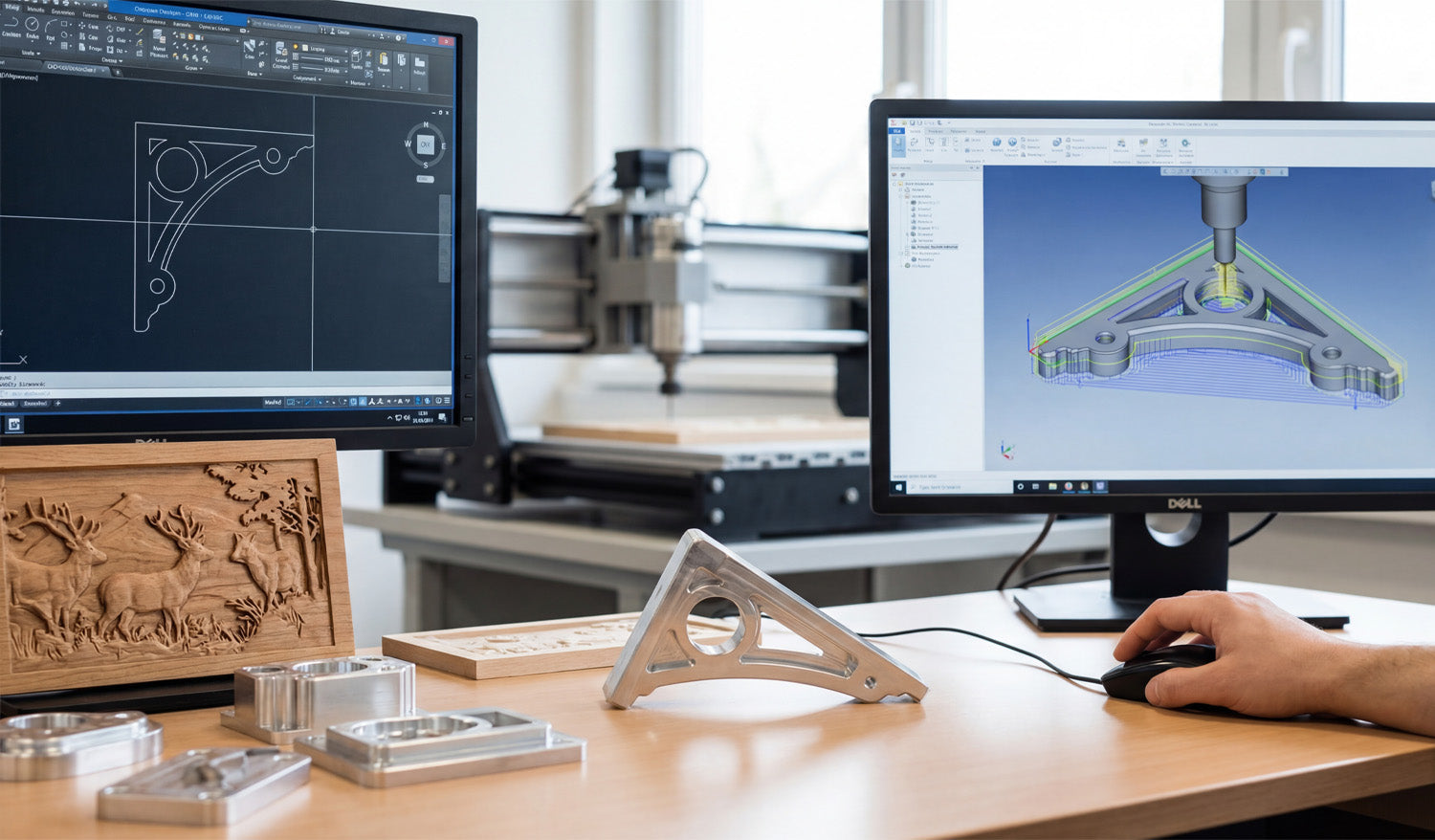
How to Create 3D CNC Models from DXF Files
Creating 3D CNC models from DXF files is a smart way to turn flat drawings into real-world parts, fixtures, molds, or carved surfaces that your router or mill can machine with confidence. How DXF Fits Into a 3D CNC Workflow DXF files are usually 2D: profiles, outlines, and flat shapes. But those same profiles are exactly what 3D CAD and CAM software need as a starting point for solid models and 3D toolpaths. DXF = 2D geometry: Contours, centerlines, holes, and part outlines. 3D model = volume: Thickness, pockets, slopes, fillets, and complex surfaces. CNC = motion: Toolpaths that follow the 3D model and generate real parts. The goal is to move smoothly from “good 2D DXF” to “clean 3D model” to “reliable 3D toolpaths.” Step 1: Clean Up the DXF Before Going 3D A messy DXF becomes an even messier 3D model. Start by fixing the basics while you are still in 2D. Confirm units and scale: Make sure the DXF is in mm or inches and that a known dimension matches real size. Close profiles: Outer outlines and inner cutouts should be true closed loops with no tiny gaps. Remove duplicates: Delete overlapping lines, arcs, and stacked geometry. Clean stray elements: Get rid of points, construction lines, and tiny scraps you do not need. Separate layers: Put different shapes (holes, outlines, centerlines) on logical layers if they are not already organized. Think of this step as “detail prep.” A few minutes of cleanup now saves hours of frustration later in 3D. Step 2: Import the DXF into 3D CAD as Sketches Most 3D CAD systems let you import DXF files directly into a sketch on a plane (usually the XY plane). Create or open a 3D CAD project. Start a new sketch on the plane where you want the part to sit. Import the DXF into that sketch instead of floating it somewhere in space. Lock the imported geometry to your origin or a reference point so your model has a clear zero. After import, run CAD tools like Trim, Extend, and Constraints to make sure the sketch is watertight and easy to extrude. Step 3: Turn 2D Profiles into 3D Features Once the DXF is a clean sketch, you can start turning lines into volume. Extrude for Flat Parts and Plates Select the closed outer profile from the DXF sketch. Use an Extrude command to give the shape thickness (for example, 10 mm or 1/4"). Cut internal profiles (holes, slots, pockets) by extruding them as “cut” operations through the solid. Revolve for Round Parts If the DXF includes half-profiles of round parts (flanges, rings, pulleys), identify the centerline. Use a Revolve operation around that axis to create full 3D bodies. Loft and Sweep for Complex Shapes Use multiple DXF sections at different heights and connect them with a Loft to create tapered or organic forms. Use a Sweep to extrude a DXF profile along a curve, for handles, rails, or decorative edges. With just extrude, revolve, loft, and sweep, most 3D CNC-ready shapes are already possible from a basic DXF. Step 4: Add Machining-Friendly Details in 3D A machinable 3D model is more than an extruded plate. Add features that reflect how cutting tools actually behave. Fillets and chamfers: Smooth sharp edges for strength, aesthetics, or better tool access. Pockets and steps: Model pockets with true depths and bottom radii to match your tools. Bosses and pads: Add raised areas where bolts, bearings, or clamps will sit. Tool access: Check that tools can reach all internal corners; add reliefs or larger radii if needed. Each tweak you make in 3D is one less surprise when you get to CAM and the real machine. Step 5: Build 3D Reliefs and Carvings from DXF Artwork For CNC routers and wood carving, DXF artwork is often the base for 3D relief models. Use DXF outlines as boundaries: Define the area where the relief will live (for example, a plaque border). Project DXF curves onto surfaces: Use them to guide sculpted areas, text, or logo regions. Convert layers into heights: Different DXF layers can represent different height zones in the 3D model. Combine with height maps if needed: Sculpt the main relief using a height map, then trim or frame it using DXF edges. The DXF provides clean edges and layout; the 3D tools provide depth, slope, and form for carving. Step 6: Move from 3D Model to CNC Toolpaths With a solid model in place, you are ready for CAM (Computer-Aided Manufacturing). The steps depend on how complex your part is. 2.5D Toolpaths from DXF-Based Models Use pocket operations for flat-bottom cavities and steps. Use contour/profile operations around outer and inner edges. Use drill cycles for holes defined in the DXF-derived model. Full 3D Toolpaths Use adaptive clearing / roughing to remove bulk material safely. Use parallel, scallop, or raster toolpaths to finish sloped or curved surfaces. Use pencil or contour finishing around tight internal features. Because the model came from a clean DXF, your toolpaths follow geometry that already makes sense in the real world. Step 7: Simulate, Check, and Correct Before Machining 3D CNC jobs are more expensive to get wrong. Simulation is your safety net. Simulate the full program to see how tools move and where material is removed. Check for collisions with clamps, fixtures, or neighboring features. Look for gouges and leftover material on critical surfaces. Verify that the stock size and zero point match how you will set up the machine. If something looks off, go back to the 3D model or DXF sketch, adjust, and regenerate toolpaths before cutting metal or wood. Step 8: Export CNC Code from the 3D-CAM Setup Once the simulation is clean, export the machine code from CAM. Choose the correct post-processor for your CNC controller (for example, Fanuc, Mach3, GRBL, or a machine-specific post). Save programs with clear names like partname_op1_roughing.nc and partname_op2_finish.nc. Keep the DXF, CAD, CAM project, and final G-code together in a labeled project folder for future reuse. At this point, your 3D CNC model has fully evolved from a flat DXF drawing into a ready-to-run machining job. Common Mistakes When Turning DXF into 3D Models Watch for these easy-to-avoid problems: Wrong scale: Importing DXF in the wrong units and building a full 3D model at 10× size. Open loops: Leaving gaps in the DXF sketch, which block extrudes and create broken solids. Too much detail: Bringing every tiny decorative line into a 3D machining project that does not need it. No thought for tools: Designing sharp inside corners that a round cutter simply cannot reach. Skipping test cuts: Going straight from screen to production without cutting a sample. Quick Workflow Checklist: DXF to 3D CNC ✔ Clean and organize the DXF (units, closed profiles, no duplicates). ✔ Import as a sketch in 3D CAD and constrain it properly. ✔ Extrude, revolve, loft, or sweep to build a solid model. ✔ Add machining-friendly details: fillets, chamfers, pockets, access radii. ✔ Create CAM toolpaths from the 3D model (2.5D and 3D as needed). ✔ Simulate and verify stock, zero, and collisions. ✔ Post-process to CNC code and run test cuts. ✔ Save everything (DXF, CAD, CAM, G-code) for future jobs. Conclusion Creating 3D CNC models from DXF files is one of the most efficient ways to connect flat drawings with real machined parts. By cleaning the DXF, importing it as a solid foundation for your 3D model, and then driving CAM from that model, you get predictable toolpaths and parts that match the original design intent. Whether you are machining fixtures, plates, brackets, or carved panels, a DXF-driven 3D workflow lets you go from sketch to finished part with far less trial and error.
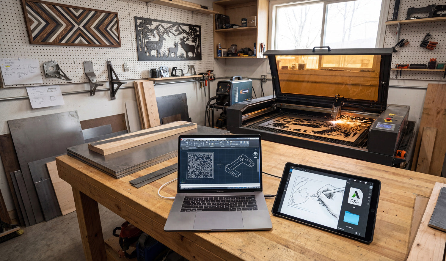
Using DXF Files for Custom CNC Fabrication Projects
Using DXF files for custom CNC fabrication projects lets you move from rough ideas and quick sketches to accurate, repeatable parts that your laser, plasma, or router can cut without drama or guesswork. Why DXF Files Are Perfect for Custom CNC Work Custom fabrication is messy by nature: every project is a little different, dimensions change, clients change their minds, and you often work with one-offs or small batches. DXF files bring order to that chaos by acting as a stable, machine-ready language between design and cutting. Vendor-neutral: DXF is supported by almost every CAD, CAM, and CNC controller. Exact geometry: Lines, arcs, and curves are stored as precise vectors, not fuzzy pixels. Easy to revise: You can tweak a few dimensions, re-export, and be cutting again in minutes. For a shop that lives on custom jobs—signs, brackets, panels, fixtures, architectural parts—DXF becomes the backbone of your workflow. From Idea to DXF: Building a Custom CNC Workflow Most custom CNC projects follow a similar path, even if the details change from job to job: Capture the concept: A sketch, email, photo, sample part, or customer drawing. Translate into CAD or vector software: Create clean 2D geometry that reflects what must be cut. Export as DXF: Save a clean, simplified version for CAM and the CNC machine. Generate toolpaths: In CAM software, turn DXF profiles into real feed rates, pierces, and depths. Test cut and refine: Make small adjustments to fit, kerf, or aesthetics based on real parts. The DXF file is the bridge in the middle of this process—stable enough to feed the machine, flexible enough to change quickly when the job evolves. Using DXF Files to Collaborate with Clients Custom jobs often start with incomplete information. A client might send a rough drawing, a screenshot, or a picture of something they liked. DXF files help you turn that into something both sides can agree on. Share approval drawings: Send a DXF or a PDF exported from your DXF so the client can review shapes and dimensions. Capture revisions clearly: Update the DXF when the client asks for changes and keep version history (v1, v2, v3). Avoid miscommunication: Exact geometry and dimensioning in DXF remove a lot of “I thought it would be bigger” problems. Once the client signs off on the DXF-based drawing, you are not guessing—you are cutting exactly what was approved. Turning Standard Designs into Custom Parts with DXF One big advantage of working with DXF files is how easily you can customize existing designs without starting from zero every time. Adjust size: Scale panels, signs, and decorative pieces while maintaining proportions and cut-ready geometry. Modify features: Add holes, slots, or mounting brackets to fit a specific project. Personalize artwork: Swap names, logos, or monograms in a sign or wall-art template. By building a library of reusable DXF templates and then customizing them per project, you keep design time low and still deliver a “custom” experience to every customer. Using Layers in DXF for Fabrication Details Custom fabrication often includes more than just cutting. You may need bend lines, weld locations, or marking details on the same part. DXF layers are perfect for this. CUT_OUTSIDE: Final outer profiles of the part. CUT_INSIDE: Holes, slots, and internal cutouts. MARK or ENGRAVE: Text, logos, part numbers, or layout marks. BEND_LINES: Lightly etched lines indicating where to bend in the press brake. REFERENCE: Centerlines, datums, construction geometry that will never be cut. In CAM, you can map each layer to a different operation (full cut, light etch, ignore) without redrawing anything, which is ideal for complex custom parts. DXF Files Across Different CNC Processes in One Shop Many fabrication shops run more than one type of CNC machine. DXF files help you feed all of them from the same core geometry. Laser or plasma: Cut flat profiles for brackets, panels, and plates. CNC router: Cut plywood, MDF, plastics, and composite panels for furniture, signs, or fixtures. Water-jet: Cut thicker or heat-sensitive materials from the same DXF outlines. You can maintain a single “master DXF” for the profile and create different CAM setups (tools, kerf, feeds) per machine or material as needed. Designing Custom Parts in DXF with Real-World Constraints Custom fabrication is not just about shape; it is about fit and function in the real world. DXF files let you design with those constraints built in. Account for kerf: Draw tabs, slots, and joint details with expected kerf and clearance in mind. Respect minimum feature sizes: Avoid thin webs or micro details that will fail on your chosen process. Align with hardware: Use bolt patterns, hole sizes, and slot shapes that match standard fasteners. When you build these rules into your DXF designs, your “custom” parts still feel standardized and predictable on the machine. Managing DXF Libraries for Custom Fabrication Over time, your custom work becomes a catalog of proven DXF files you can reuse and adapt. Organize by category: Signs, brackets, gussets, fixtures, architectural, art panels, etc. Store master and production versions separately: Editable source vs. clean cut-ready DXF. Tag files with notes: Material used, ideal thickness, and any special cutting instructions. This library turns past projects into future shortcuts: when a new customer asks for something similar, you start from a proven DXF instead of a blank screen. Common Pitfalls to Avoid in Custom DXF Projects Custom projects can go sideways fast if the DXF is not prepared carefully. Watch out for: Open contours: Gaps in profiles that cause incomplete cuts. Duplicate lines: Overlapping geometry that makes the machine cut the same path twice. Hidden tiny shapes: Tiny islands or specks from tracing that add time and no value. Unclear layers: Everything on one layer, making it hard to separate cutting and marking operations. A quick pre-flight check of the DXF before CAM—especially on custom jobs—saves time, material, and customer frustration. Real-World Example: Custom Bracket for a One-Off Build Imagine a customer needs a special bracket to mount a new piece of equipment on an older frame. You measure the existing mounting points and sketch the bracket concept. You create a 2D profile in CAD, then export a DXF with slotted holes for adjustment. You run a quick test cut, check fit, and tweak slot length or hole diameter if needed. Once the bracket fits perfectly, you save that DXF in your library for future retrofits. From then on, what started as a one-off becomes a repeatable product in your shop—all driven by a clean DXF file. Conclusion Using DXF files for custom CNC fabrication projects turns loose ideas into cut-ready geometry that your machines understand. With DXF, you can collaborate clearly with clients, reuse proven designs, manage multi-step fabrication details on layers, and feed different machines from the same core profiles. For any shop that thrives on custom work, DXF is not just another file format—it is the foundation of a faster, more reliable, and more profitable CNC workflow.
Why You Should Choose DXF Files Over Other Formats for CNC Projects
Choosing DXF files over other formats for CNC projects keeps your geometry clean, your workflow predictable, and your machines compatible across different software and hardware. File Format Can Make or Break a CNC Job If you run a CNC machine long enough, you see the same pattern: good designs ruined by the wrong file format. Someone sends a logo as a tiny JPG, a drawing as a proprietary CAD file nobody can open, or a vector with broken paths. You spend more time fixing files than cutting parts. DXF (Drawing Exchange Format) was created to solve exactly this problem. It acts as a common language between CAD, CAM, and CNC systems, especially for 2D cutting like laser, plasma, router, and water-jet. 1. DXF Is Designed for Exact CNC Geometry DXF stores geometry as real vectors: lines, arcs, circles, and splines with exact coordinates. That makes it ideal for CNC cutting. No pixel guessing: Unlike JPG or PNG, DXF does not need to be “traced.” The shapes are already clean vectors. True arcs and circles: Holes, slots, and radii stay round and smooth, not made of tiny jagged segments. Consistent dimensions: What you draw at 100 mm in CAD arrives as 100 mm in CAM when units are set correctly. For tight fits, bolt patterns, and precise contours, this level of accuracy is non-negotiable. 2. DXF Works with Almost Every CAD, CAM, and CNC System One of the biggest reasons to choose DXF is simple: everybody understands it. Most CAD programs can export and import DXF without extra plugins. Most CAM packages can read DXF directly for 2D toolpaths. Many laser and plasma controllers import DXF as a primary format. That means you can design in one program, nest in another, and cut on a different machine brand without redrawing from scratch or fighting conversions. 3. DXF Beats Raster Images for CNC Every Time People often start with logos, artwork, or photos in formats like JPG or PNG. Those are fine for screens, but not for CNC machines. Raster formats: Store pixels. Your software must guess where edges are when you trace them, creating noisy paths. DXF: Stores curves and lines directly. No tracing, no “close enough” edges, no random bumps in your toolpath. If you begin with a raster image, the best practice is to convert it into clean vector artwork and export as DXF for CNC. That conversion step is where you fix the geometry—DXF is where you lock it in. 4. DXF Is More CNC-Friendly than Many Native CAD Formats Native CAD files (DWG, proprietary 3D formats, parametric models) are great for engineering, but they are not always ideal for the shop floor. They may require the same software (and license) used to create them. They can contain a lot of extra data you do not need for cutting. They sometimes import unpredictably into third-party CAM systems. DXF is lighter and focused on 2D geometry. When your goal is to cut a flat part, not rebuild a parametric model, DXF is usually the most direct route from design to toolpath. 5. DXF Handles Layers and Colors for CNC Operations One of DXF’s biggest superpowers is layer support. This matters a lot for multi-step CNC jobs. You can create separate layers for outside cuts, inside cuts, engraving, scoring, and reference geometry. Many laser and plasma controllers can map colors or layers directly to different power, speed, or pierce settings. Reference geometry (centerlines, dimensions, notes) can live in the file without being cut. Other vector formats like SVG can handle layers too, but DXF is the one most CAM and CNC tools were built to understand in a manufacturing environment. 6. DXF Plays Nicely with Kerf Compensation and Toolpaths For CNC cutting, geometry is only half the story. You also need to consider kerf (cut width) and inside/outside compensation. DXF stores clean closed profiles that CAM software can easily offset for kerf. Inside and outside contours are easier to detect when shapes are well-defined in DXF. Plasma and laser CAM systems are typically tuned to work best with DXF inputs. Other formats might carry vectors too, but DXF has become the “native language” for 2D kerf-based processes in many shops. 7. DXF Files Are Easier to Inspect and Troubleshoot When a CNC job fails, you often ask: “Is it the machine, the CAM settings, or the file?” With DXF, the file part is easier to check. Free viewers and basic CAD tools can open and zoom into DXF to inspect geometry. You can quickly spot open paths, duplicate lines, or stray entities and fix them. Because DXF is widely documented, it is simpler to understand what is actually inside the file. Trying to debug native, locked-down formats or flattened artwork is usually harder and slower. 8. DXF Supports Long-Term Storage and Reuse File formats come and go as software changes, but DXF has been around for decades and is still the standard in many CNC workflows. It is well documented, so future tools will likely continue to support it. It is human-readable at a basic level (text-based variants), giving you some protection against format lock-in. You can safely archive DXF libraries and expect them to be usable years later, even if your CAD system changes. That makes DXF a smart choice for long-term design libraries, product lines, and recurring CNC jobs. 9. DXF Works Well Alongside Other Formats Choosing DXF does not mean you must abandon every other format. Instead, you use each one where it makes sense: AI / SVG: For creative artwork and design stages. Native CAD: For 3D modeling, assemblies, and parametric design. DXF: As the final, clean 2D profile you send into CAM and CNC. Think of DXF as the “production language” for your cutting machines—a stable, CNC-ready version of whatever design path you used to get there. 10. When DXF Should Be Your Default Choice If your project involves 2D cutting or engraving on a CNC machine, DXF is almost always the safest default. It is especially strong when: You share files between different shops, partners, or machines. You run laser, plasma, water-jet, or router tables for flat parts. You maintain a large library of reusable designs that must outlive any single software tool. In these scenarios, other formats may still appear in your workflow, but the file that feeds the machine is typically DXF. Quick Comparison: DXF vs Other Common Formats Format Best For CNC Suitability DXF 2D CNC cutting, CAD exchange Excellent – native choice for many CAM/CNC tools JPG/PNG Photos, mockups, web Poor – needs tracing, low precision SVG/AI Artwork, logos, design Good for design, but less universal in CAM than DXF Native CAD (DWG, etc.) Engineering, 3D models Requires matching software; extra conversion step Conclusion DXF files give CNC projects a huge advantage: precise vector geometry, universal compatibility, clean layer control, and long-term reliability. While other formats still have a place for design, artwork, and 3D modeling, DXF is the format you can trust when it is time to move from screen to steel, wood, acrylic, or aluminum. Choosing DXF as your standard for CNC projects means fewer surprises, faster setup, and more consistent results on every job.
How to Create Perfectly Optimized DXF Files for CNC Plasma Cutting
Creating perfectly optimized DXF files for CNC plasma cutting is less about “pretty artwork” and more about smart geometry, correct kerf planning, and designs that match how plasma really behaves on steel, stainless, or aluminum. Why Plasma Needs Special DXF Optimization Plasma cutting is powerful but not delicate like a fine laser. It has a wider kerf, more heat, and slightly rougher edges. If your DXF file is built like it is going to a laser or a router, you will fight: Blown-out small details and thin bridges. Out-of-round holes and distorted slots. Warped parts from long, unplanned cuts. Parts falling into the table mid-cut because the skeleton is weak. Optimizing DXF files for plasma means designing shapes, holes, and text that cut cleanly at plasma scale and thickness—not just on your monitor. Step 1: Lock In Units, Material, and Thickness Before You Draw Great plasma DXF work starts before the first line is drawn. Pick your units: Decide on millimeters or inches and set your CAD/vector software accordingly. Choose material and thickness: 3 mm mild steel, 10 mm plate, 1/4" aluminum, etc. This will drive your minimum feature sizes. Note your machine’s kerf range: Different nozzles and amps produce different kerf widths. Write these three things down (units, material, thickness) in project notes. Every design decision you make in the DXF should respect them. Step 2: Design Plasma-Friendly Geometry Plasma loves bold, sturdy shapes and hates fragile, tiny details. Use that rule to guide your DXF design. Minimum web/bridge width: Keep thin connections and webs clearly larger than the kerf and strong enough to survive slag and cleanup. Simplify fine detail: Remove tiny spikes, hairline gaps, and micro cutouts that will just burn away or fuse. Round sharp internal corners: Add small radii; plasma naturally rounds corners, so design with that in mind. Use bold shapes for small parts: The smaller the part, the more robust it should be in the DXF. If a detail would be hard to cut by hand with a plasma torch, it is probably too small for CNC plasma at production speeds. Step 3: Plan for Good Hole and Slot Quality Holes and slots are where plasma shows its personality. If your DXF does not respect plasma rules, holes end up tapered, egg-shaped, or undersized. Respect minimum hole size: Avoid tiny holes that are close to your kerf width. As a simple rule of thumb, make hole diameters significantly larger than the kerf and at least a bit larger than material thickness. Use true circles in the DXF: Draw holes as real circles or arcs, not as rough polygons or traced shapes. Keep holes away from edges: Do not push holes too close to outside profiles where heat can distort them. Oversize holes slightly if needed: If real cuts come out tight, you can build that correction into the DXF for repeat jobs. The more consistent your DXF hole geometry is, the easier it is to dial in repeatable plasma settings for clean, round holes. Step 4: Clean the DXF Geometry Until It Is “Boring” A perfectly optimized plasma DXF looks boring to a CAD nerd—and that is good. Plasma loves clean, simple geometry. Delete duplicates: Remove overlapping lines and arcs that would cause double cuts and ugly edges. Close all contours: Make sure every outer profile and inner cutout is a fully closed loop. Remove junk: Delete construction lines, tiny islands, specks, and artifacts from tracing. Join polylines: Convert many small segments into continuous polylines wherever possible. Simplify curves: Use “simplify path” tools to reduce node count without changing the visible shape. The goal is geometry your CAM software can read in one pass, without guessing or patching gaps for you. Step 5: Use Layers to Separate Cut Types Even if your plasma jobs are “just cutting,” layers make your DXF safer and faster to program. Create layers such as CUT_OUTSIDE, CUT_INSIDE, MARKING, and REFERENCE. Put outer profiles (final part outlines) on CUT_OUTSIDE. Place holes, slots, and inner cutouts on CUT_INSIDE. Use MARKING for layout marks, bend lines, or weld location marks. Keep centerlines, dimensions, and notes on REFERENCE so they are never cut. With this structure, you can quickly map each layer to different plasma settings or decide to ignore layers like REFERENCE in CAM. Step 6: Think Ahead About Pierce Points and Lead-Ins Plasma cuts do not start magically. Each path begins with a pierce that creates a rougher spot. If your DXF does not leave room for that pierce, you lose precision or aesthetics. Avoid pierces on critical edges: Give CAM room to place pierces away from tight corners or visible design areas. Leave “landing zones”: In your shapes, consider where lead-ins can safely start and end without leaving marks in important areas. Use loops or small tabs if needed: Slight design tweaks can give your software a safe place to enter and exit the cut. You do not draw lead-ins inside the DXF, but you design the shapes so that good lead-ins are possible and obvious. Step 7: Design for Skeleton Strength and Part Stability On plasma tables, the “skeleton” (what is left of the sheet) matters. A perfect DXF does not cause the skeleton to collapse or eject parts prematurely. Avoid ultra-thin slivers: Long, narrow strips between parts twist and catch on the torch head. Stagger cuts: When nesting, avoid placing many long, parallel cuts side by side in the same area. Plan tabs for small parts: For tiny parts, add tabs in CAM and design shapes that can accept them without ruining the look. Keep key support areas intact: Do not cut away everything in one region; leave material to support later cuts. Designing with skeleton behavior in mind is one of the biggest differences between “art DXF” and “production plasma DXF.” Step 8: Match Detail Level to Material Thickness The same DXF should not be used blindly for 3 mm sheet and 20 mm plate. Thickness changes everything. Thin material (sheet): You can keep more detail, but watch out for heat distortion and flimsy bridges. Thick plate: Simplify internal detail, beef up text and ornaments, and avoid tiny cutouts that will trap dross. Per-thickness variants: Consider saving separate DXF versions tuned for specific thickness ranges. A design that looks perfect in 3 mm can be a nightmare in 12 mm. Your DXF library is stronger when you create versions optimized for the real plate you cut. Step 9: Export a Plasma-Friendly DXF Version Many CAM and controller packages are happiest with older, simpler DXF flavors. Export as a widely supported version such as R12 or R14 DXF when possible. Strip out unneeded items: hatches, dimensions, 3D entities, and embedded images. Verify that layers, colors, and line types came across correctly in a DXF viewer. The lighter and cleaner your exported DXF is, the fewer headaches you will have at the plasma table. Step 10: Test Cut, Measure, and Lock In the “Production” File No DXF is truly “perfectly optimized” until it has been cut and checked at least once on the real machine. Run a test cut on scrap or offcut material using your export DXF. Measure holes, slots, tab fits, and overall sizes with calipers. Note which features are too fragile, too tight, or not worth the cut time. Tweak the DXF as needed (hole diameters, bridge widths, simplified detail) and save a new version marked as production ready. From that point on, your plasma DXF is not just “nice artwork”—it is a proven, optimized pattern you can run again and again with confidence. Quick Plasma DXF Checklist Before you send a DXF to your CNC plasma cutter, ask: ✔ Units, material, and thickness are clearly defined. ✔ All profiles are closed, and there are no duplicate or stray entities. ✔ Detail level matches plasma kerf and material thickness. ✔ Holes and slots are drawn as true circles/slots and sized for real-world cutting. ✔ Layers cleanly separate outside cuts, inside cuts, marking, and reference geometry. ✔ Geometry allows safe pierce locations and lead-ins away from critical edges. ✔ The nested layout preserves skeleton strength and small-part stability. ✔ At least one test cut has been made, measured, and used to refine the final DXF. Conclusion Creating perfectly optimized DXF files for CNC plasma cutting is about designing for the reality of plasma—not for the perfection of the CAD screen. When you control geometry, hole quality, detail level, skeleton behavior, and DXF export, your plasma table stops being a guessing game and becomes a predictable, efficient production tool that turns bold vector designs into strong, clean metal parts.
Why DXF Files Are a Must for High-Precision CNC Projects
DXF files are essential for high-precision CNC projects because they carry clean, exact vector geometry from your CAD software to the machine without guesswork, distortion, or hidden surprises. High Precision Starts with Reliable Geometry Every tight-tolerance CNC part begins as a drawing. If that drawing is fuzzy, approximate, or full of errors, the finished part will be the same. DXF (Drawing Exchange Format) was created to move precise 2D geometry between different systems while keeping: Exact coordinates for lines, arcs, and curves. Stable units (millimeters or inches) that do not shift on import. Predictable entities that CAM software can turn into accurate toolpaths. For high-precision work—fixtures, plates, jigs, brackets, and templates—this level of geometric reliability is non-negotiable. DXF vs. Image-Based Files: No More Guessing One of the easiest ways to lose precision is to start from the wrong file type. Bitmaps and screenshots may look fine on screen, but they force your software to guess at edges. Raster images (JPG, PNG, TIFF) store pixels, not coordinates. When you trace them, tiny stair-steps and noise become part of the geometry. DXF files store pure vector data. Every corner and radius is defined by numbers, not by pixel edges. That difference matters when you are cutting tight-fitting tabs, aligned bolt patterns, or parts that must repeat perfectly from one batch to the next. Consistent Units and Scale for Tight Tolerances Precision is impossible if you are not sure how big the part really is. DXF is designed to keep units and scale under control. You define units once in CAD (mm or inches); the DXF passes that geometry directly to CAM. Dimensions and reference lengths in the DXF let you verify size after import. Scaling mistakes—parts 10× too big or small—are easy to spot and avoid. For high-precision CNC work, this consistency means less time measuring and more time cutting parts you can trust. Layer Control for Multi-Step Precision Jobs High-precision projects often mix different operations on the same part: through cuts, counterbores, engraving, and reference marks. DXF layers make this complexity manageable. Separate layers for outside profiles, pockets, holes, engraving, and reference edges. Each layer can map to different tools, depths, feeds, and speeds in CAM. Reference geometry (centerlines, datums, alignment marks) stays in the file without ever being cut. This layer structure helps you align critical features, maintain datums, and repeat complex setups with the same accuracy every time. Exact Curves for Smooth Toolpaths High precision is not just about hitting the right size—it is also about smooth motion. DXF describes arcs, circles, and splines numerically, so CAM can generate continuous, flowing toolpaths. True arcs cut cleaner holes and slots than lots of tiny line segments. Consistent radii reduce stress concentrations and make parts easier to finish. Optimized node counts avoid “stop-and-go” motion that leaves faceted edges on tight curves. When your high-precision design includes bearing fits, dowel pin holes, or smooth mating surfaces, DXF-based arcs make the difference between “close enough” and “right on size.” DXF as the Glue Between Different CAD/CAM Systems Many high-precision environments use more than one software tool: one for design, another for simulation, and a third for CAM or nesting. DXF is the common language that keeps geometry consistent across all of them. Design in your main CAD software, export a DXF, and import it into whatever CAM is best for your machine. Share DXF drawings with suppliers or partners and know they can open them on their own systems. Move legacy parts from older CAD tools into new workflows without redrawing from scratch. When teams, machines, and software change over time, DXF protects the precision built into your original design. Supporting Tight Fits, Jigs, and Repeatable Fixtures Some of the most demanding CNC parts are not flashy—they are the jigs and fixtures that hold everything together. DXF fits naturally into this world. Fixture plates: Bolt patterns and dowel layouts stay aligned between different parts and revisions. Drill templates: Hole locations transfer from CAD to the shop floor without tape measures and layout dye. Assembly jigs: Slots, pins, and stops line up exactly, job after job. Once a DXF-based fixture proves accurate on the machine, you can reuse and re-cut it on demand with complete confidence. Kerf and Compensation: Designing for Real-World Accuracy DXF files are also a natural place to embed kerf-aware geometry for high-precision fits. Slots and tabs can be drawn with the expected kerf and clearance already considered. Standard hole sizes in the DXF match standard tool diameters or kerf-compensated laser/plasma paths. Outer profiles and inner features are ready for inside/outside compensation without guesswork. When CAD, DXF, and CAM all agree about kerf and tolerances, you spend far less time filing and reworking “almost right” parts. Traceability and Documentation for Quality Work High-precision work often needs traceability—especially in aerospace, automotive, and industrial applications. DXF supports this kind of disciplined workflow. Each revision of a DXF can be tied to a drawing number, date, and version in your documentation. Inspection teams can use the DXF as a reference for CMM programs or manual checks. Suppliers can receive the same DXF that your internal team uses, reducing misinterpretation. This combination of clear geometry and documented revisions helps you prove that parts were made to the correct design, not just “close enough.” Real-World Example: High-Precision Mounting Plate Imagine a mounting plate that connects a motor to a gearbox. The bolt pattern, pilot diameter, and key slots must all align perfectly. With a well-prepared DXF: The bolt circle and center bore come directly from CAD, not from rough measuring. Toolpaths follow true circles and arcs, producing round, repeatable fits. Multiple plates cut from different batches match each other within the expected tolerance. Without DXF-level control, you are back to transferring hole locations by hand and hoping they line up from job to job. DXF in Mixed 3D/2D Precision Workflows Even in 3D-heavy environments, precise 2D profiles still matter: for gaskets, shims, cover plates, base plates, and laser-cut blanks. CAD users extract 2D views or sections from 3D models and export them as DXF. Those DXF profiles drive laser, water-jet, or router tables to produce finished blanks. The final parts fit into larger assemblies with no manual shaping or adjustment. In this mixed workflow, DXF is the bridge between 3D design intent and flat, high-precision components on the shop floor. Conclusion DXF files are a must for high-precision CNC projects because they deliver exactly what tight-tolerance parts need: clean vectors, consistent units, layer-based control, and a stable bridge between design and machining. Whether you are cutting small brackets, complex fixtures, or mission-critical plates, a carefully prepared DXF lets your CNC machines do their best work—accurate, repeatable, and ready for serious production.
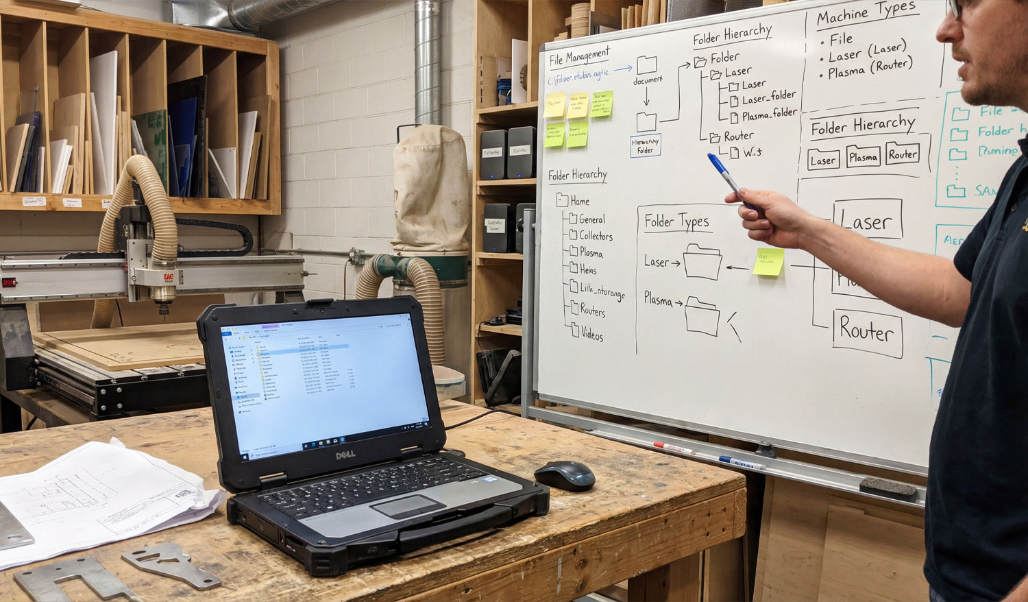
Tips for Organizing and Storing Your DXF Files for CNC Machines
Well-organized DXF files can make your CNC shop feel faster and calmer. Instead of hunting through random folders, you always know where each design lives, which version is current, and which file is ready for which machine. Why DXF Organization Matters More Than You Think DXF files are the language your CNC machines speak. When they are scattered across hard drives with names like new_11_final.dxf, you waste time on: Searching for the “right” version before every job. Accidentally cutting outdated or untested designs. Duplicating work because you cannot find past projects. A simple folder structure, clear file names, and a basic backup plan can remove most of this chaos and let you focus on cutting parts, not chasing files. 1. Start with a Simple, Repeatable Folder Structure You do not need a complicated system—just one you can actually stick to. A good starting point for DXF files might look like this: DXF Library Laser Plasma Router Mill Inside each machine folder, group designs by use or style: Laser → Signs, Wall Art, Logos Plasma → Brackets, Yard Art, Fire Pits Router → Furniture Parts, Jigs, Inlays Keep it logical and consistent. The test is simple: can someone else on your team find a file in under 30 seconds? 2. Separate “Master” Files from “Production” Files One of the best habits you can build is treating design and production files differently. Master files: Your fully editable originals (CAD, AI, SVG). These may contain construction lines, notes, and extra detail. Production DXF: Clean, simplified files ready for import into CAM or your CNC controller. Example folder layout: DXF Library Master Production This approach lets you edit and experiment without breaking the file that the shop floor uses every day. 3. Use Descriptive, Machine-Friendly File Names File names are tiny labels that can carry a lot of useful information. A good DXF name answers at least three questions: What is it? What size is it? What material or thickness is it for? For example: wolf_wall_art_600mm_steel3mm_v2.dxf bracket_L_100x50_aluminum5mm_v1.dxf You can also add the target machine when it matters: panel_pattern_large_laser_only_v3.dxf bracket_set_router_plywood18mm_v2.dxf Clear names reduce questions and miscuts, especially when you run multiple machines and materials. 4. Version Your DXF Files Before Things Get Messy Designs evolve. A joint is too tight, a slot is too loose, or a logo changes. If you do not manage versions, your DXF folder slowly becomes a puzzle. Add a simple version tag: v1, v2, v3 at the end of the name. Only mark one file as the current production version (for example, in a text note or by moving old versions to an Archive subfolder). When a change is made because of a real test cut, always bump the version number. Small shops often skip versioning until they regret it. Start early while your library is still manageable. 5. Organize by Machine, Material, and Thickness If you cut the same design on different machines or materials, give each combination its own home. By machine: Keep separate folders for Laser, Plasma, Router, and Mill. By material: Inside each, use folders for Steel, Aluminum, Stainless, Plywood, Acrylic, etc. By thickness: For example, Steel_3mm, Steel_6mm, Birch_12mm. Why? Because kerf, fit, and toolpaths often change with thickness. Keeping these variants separated avoids mixing “steel 3 mm” cut files with “steel 10 mm” jobs. 6. Keep Reference Material and CAM Files Nearby DXF files rarely live alone. They are usually part of a small “bundle” for each project. DXF folder: Clean geometry ready for CAM. CAM folder: Toolpath files or project files for your CAM software. Previews: JPG or PNG images that show what the final part should look like. Notes: A text file with best-known feeds, speeds, or power settings. A simple structure like this turns each job into a self-contained package you can pick up months later with minimal guesswork. 7. Use Cloud or NAS Storage for Shared Access If more than one person is using your DXF library, local storage on a single PC quickly becomes a bottleneck. Use a shared network drive or NAS so all shop computers access the same “truth.” Consider a cloud-synced folder for backup and remote access. Limit who can edit “Master” folders; give operators read-only access where appropriate. This reduces the risk of “secret” copies living on USB sticks and laptop desktops where they are never updated or backed up. 8. Back Up Your DXF Library Like It Is Business-Critical (Because It Is) Your DXF files represent hours or years of work. Treat them like an asset, not an afterthought. Set up automatic daily or weekly backups of your DXF and CAM folders. Keep at least one backup off-site or in the cloud in case of fire, theft, or hardware failure. Test your backup by restoring a sample project occasionally. A good backup policy means a failed hard drive is an inconvenience, not a disaster. 9. Use a Simple Index or Catalog for Large Libraries Once your DXF collection grows beyond a few hundred designs, a basic catalog makes life easier. Create a spreadsheet or simple database listing: File name Category (animals, signs, brackets, fixtures, etc.) Target machine and material Notes about sizes or popular variations Add a column for “approved for production” so you know which designs have been test cut. This does not have to be fancy. Even a basic index helps you remember what you already have before you redraw the same idea again. 10. Standardize Your Workflow for New DXF Files Finally, make sure every new file enters your system the same way. For example: Design or edit in CAD/vector software. Save the editable master in the Master area. Export a clean DXF to the correct Production folder (Laser/Plasma/Router/Mill). Rename according to your file-naming rules. Run a test cut, then update the version number if you make adjustments. When this process is documented and followed by everyone, your DXF library stays organized automatically instead of slipping into chaos over time. Conclusion Organizing and storing DXF files for CNC machines is not about perfection; it is about consistency. A clear folder structure, descriptive file names, simple version control, shared storage, and regular backups turn your DXF collection into a powerful, reliable asset. With a little discipline now, you will spend far less time searching for files and far more time running profitable CNC jobs.
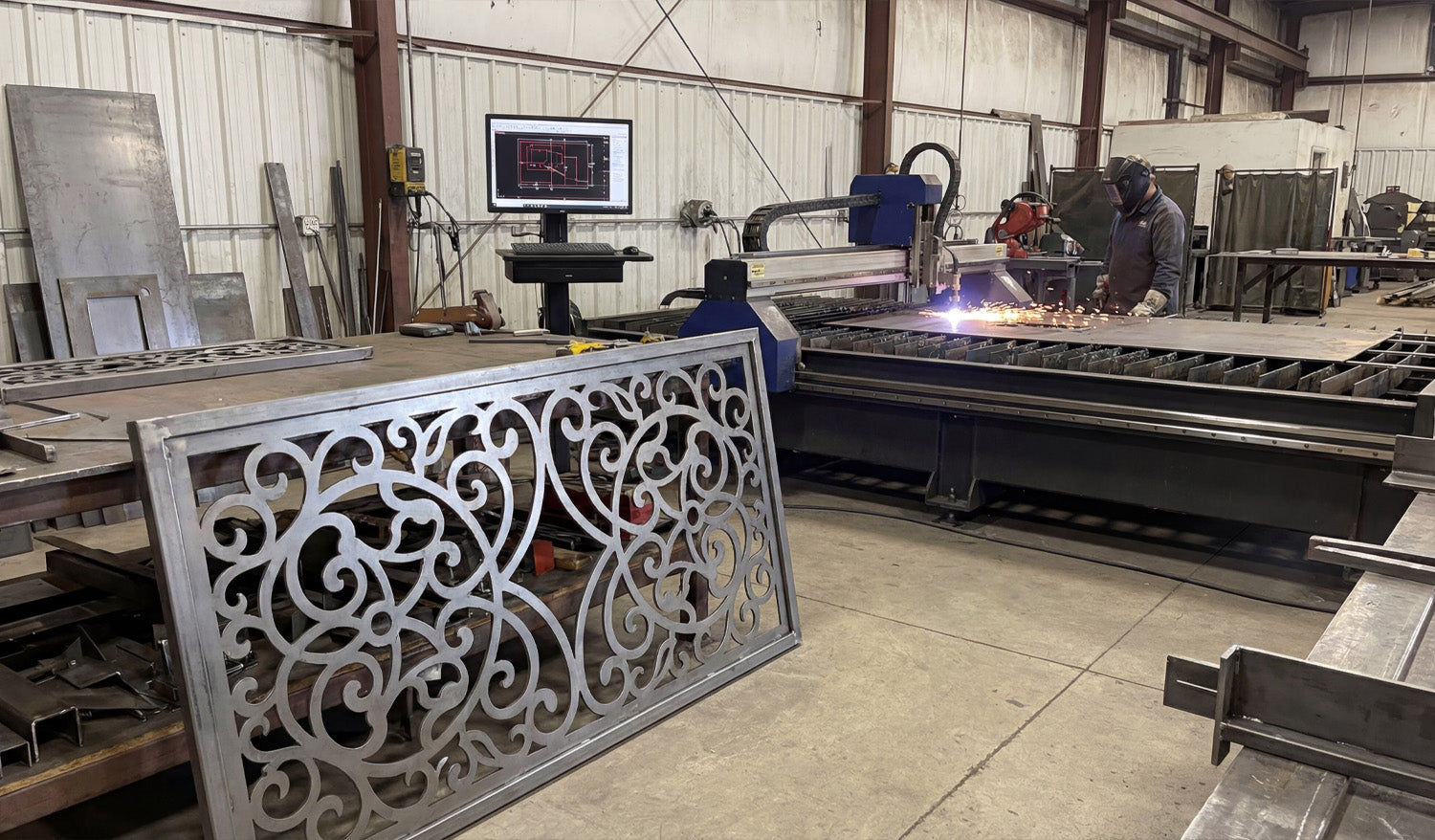
How to Use DXF Files for Efficient CNC Cutting of Complex Shapes
Using DXF files for efficient CNC cutting of complex shapes is all about combining clean vector design, smart nesting, and machine-aware toolpaths so your laser, plasma, router, or mill can handle detailed parts without wasting time or material. Why DXF Files Are Ideal for Complex CNC Shapes DXF (Drawing Exchange Format) files store geometry as vectors—lines, arcs, and curves—rather than pixels. This makes them perfect for complex CNC cutting because: Curves and contours remain smooth at any size. Toolpaths can follow precise edges instead of “guessing” from a bitmap. Layers and colors can represent different operations (cut, engrave, score). Almost every CAD, CAM, and CNC controller can import DXF files. When your DXF files are prepared correctly, even very intricate patterns can be cut reliably and repeatedly across different machines and materials. Step 1: Design Complex Shapes with CNC in Mind Efficient cutting begins at the design stage. If you know a shape will be used for CNC cutting, design it with real-world constraints from the start. Define the purpose: Is it decorative art, structural, a sign, or a functional part in an assembly? Choose the machine: Laser, plasma, router, or mill—each has different minimum feature sizes and kerf. Pick the material: Steel, aluminum, wood, acrylic, MDF, etc., all respond differently to complex cuts. By setting these parameters early, you can avoid over-detailing areas that your machine or material cannot handle efficiently. Step 2: Keep Geometry Clean and Connected Complex shapes often involve many curves, cutouts, and internal details. Clean geometry is critical for efficiency. Close all contours: Ensure every outer profile and inner cutout is a closed loop—no tiny gaps. Remove duplicates: Delete overlapping lines and arcs that can cause double cuts. Eliminate stray elements: Clean out tiny fragments, construction lines, and unused blocks. Join related segments: Convert small segments into continuous polylines wherever possible. Clean DXF geometry reduces toolpath calculation time and prevents weird behavior on the CNC machine, especially around complex details. Step 3: Optimize Node Count on Curves and Contours Complex shapes tend to accumulate a lot of nodes (control points), especially if they are traced from images. Too many nodes slow down CAM and create choppy motion. Use your CAD or vector software’s simplify or optimize curve tools. Set simplification tolerances so the visual shape stays accurate but uses fewer points. Convert “stair-stepped” outlines from tracing into smoother arcs and splines. Focus on dense areas: decorative borders, filigree, and fine patterns. Optimizing node count helps your CNC machine follow complex paths smoothly and efficiently without changing the overall look. Step 4: Use Layers to Separate Complex Operations Complex DXF designs often combine different operations: through cuts, engraving, scoring, and reference geometry. Layers keep this under control. Create layers for CUT_OUTSIDE, CUT_INSIDE, ENGRAVE, SCORE, and REF. Place each element of the complex shape on the correct layer as you design. Assign distinct colors per layer if your CAM or controller maps colors to settings. Put dimensions and construction marks on a reference layer that will never be cut. Layered DXF files let you quickly assign power, speed, and depth settings to different parts of a complex design in just a few clicks. Step 5: Match Detail Level to Machine and Material Not every detail that looks great on-screen will cut cleanly or efficiently on your machine. For complex shapes, it is vital to align detail with reality. Laser: Can handle very fine detail, but avoid micro features that are smaller than the kerf or cause weak bridges. Plasma: Needs stronger, thicker details. Remove tiny islands and thin webs that will warp or blow out. Router: Limited by tool diameter; internal corners need radii or dogbones to be cut accurately. Mill: Complex contours may require multiple tools and passes; avoid impossible-to-reach recesses in 2D contour work. For efficient cutting, simplify any detail that your process cannot reliably reproduce or that dramatically slows the job without adding real value. Step 6: Plan Kerf, Bridges, and Minimum Features Complex shapes look impressive, but they must survive cutting and handling. Design your DXF with kerf and minimum feature sizes in mind. Know your kerf width for each process and material. Ensure bridges and thin webs are wider than the kerf and strong enough after cutting. Set minimum feature sizes (gap width, hole diameter, text thickness) for each machine type. Adjust critical fit features (tabs, slots, joints) for expected kerf compensation. Kerf-aware DXF designs let your complex shapes stay strong and functional instead of falling apart at the table. Step 7: Nest Complex Shapes for Efficient Material Use When cutting multiple complex shapes from sheet material, nesting is key to efficiency. Arrange shapes to maximize material usage and minimize scrap. Rotate and mirror parts where allowed to fit them more tightly together. Maintain safe spacing between complex contours to avoid heat buildup or collisions. Group similar shapes or mirrored pairs to simplify cutting order. A well-nested DXF layout for complex shapes can significantly reduce material cost and cutting time, especially on larger jobs. Step 8: Assign Smart Lead-Ins, Lead-Outs, and Cut Order Complex shapes often have many internal cutouts, spikes, and tight curves. Toolpath strategy matters as much as the geometry. Use lead-ins and lead-outs away from critical edges to avoid visible marks. Cut internal features first (holes, slots, inner details), then outer profiles last. For thin materials or small complex parts, consider tabs to keep parts from tipping or moving. Optimize cut order to minimize rapid moves and reduce the chance of heat distortion. Good toolpath planning turns a complex DXF drawing into a smooth, efficient CNC job instead of a chaotic cut sequence. Step 9: Simulate Before Cutting Complex DXF Jobs Simulation is especially important when shapes are intricate and toolpaths are dense. Simulate the full cut path in your CAM software. Watch for unexpected jumps, collisions, or strange tool behavior. Check that inside/outside compensation is correct for all contours. Review estimated cut time and see if any areas are over-detailed for the result you need. A few minutes of simulation can save sheets of material and hours of troubleshooting on complex CNC jobs. Step 10: Test on Scrap and Refine the DXF Even with a great DXF and well-planned toolpaths, complex shapes almost always benefit from one test run. Cut a small section or downsized version of the design on scrap material. Check edge quality, sharpness of detail, and strength of thin areas. Adjust power, speed, and kerf compensation as needed. Refine the DXF by thickening weak features or simplifying overly dense detail. Use what you learn from test cuts to improve both the design and the process. Save updated versions of your DXF with clear version numbers. Quick Checklist for Efficient CNC Cutting of Complex DXF Shapes Before running a complex DXF job, make sure: ✔ Units and scale are correct and verified with a known dimension. ✔ Geometry is clean: no gaps, duplicates, or stray entities. ✔ Node count on curves is optimized for smooth motion. ✔ Layers clearly separate different operations (cut, engrave, score, reference). ✔ Detail level matches your machine’s kerf and minimum feature size. ✔ Nesting is efficient and respects safe spacing. ✔ Toolpaths use smart lead-ins, lead-outs, and cut order. ✔ Simulation and at least one test cut have been completed. Conclusion Using DXF files for efficient CNC cutting of complex shapes is not just about having powerful machines; it is about feeding those machines smart, clean, and well-organized designs. By cleaning geometry, optimizing curves, using layers, planning kerf and feature sizes, nesting strategically, and testing before production, you can cut even very intricate patterns with confidence. Do this consistently, and your DXF workflow will turn complex shapes into reliable, profitable CNC projects on every job.
What Makes a Perfect DXF File for CNC Cutting?
A perfect DXF file for CNC cutting is clean, accurate, and truly machine ready, so your laser, plasma, router, or mill can cut fast and produce consistent high quality parts. What Do We Mean by a “Perfect” DXF File? In CNC work, a perfect DXF file is not just a pretty drawing. It is a 2D vector file that is ready to go straight into CAM or your machine software with minimal cleanup. A perfect DXF file should: Import at the correct real world size and units. Contain only the geometry you actually need to cut or engrave. Have clean, closed profiles and no hidden problems. Be organized in layers so operations are easy to assign. Respect the limits of your CNC machine and material. 1. Correct Units and Real World Scale The first rule of a perfect DXF file is simple: it must come in at the right size. Choose one unit system (millimeters or inches) and stick to it. Set your CAD or vector software to that unit before drawing anything. Include at least one known dimension (for example, a 100 mm or 4 inch reference) so you can confirm scale after import. If the DXF loads ten times bigger or smaller than expected, it is not CNC ready yet. A perfect DXF never makes you guess about its size. 2. Clean, Closed Geometry Most cutting problems come from messy geometry. A perfect DXF file has clean, connected shapes that CAM software can understand. Closed profiles: Outer outlines and inner cutouts are fully closed loops, not almost closed with tiny gaps. No duplicate lines: There are no overlapping segments that would cause double cutting. No stray entities: Tiny leftovers, points, construction lines, and unused blocks are deleted. Polylines when possible: Related segments are joined into continuous polylines for smoother toolpaths. Clean geometry means no surprise breaks in cuts and no strange toolpath behavior on the CNC machine. 3. Optimized Node Count for Smooth Motion Too many nodes (control points) make your machine move in a stop and go pattern and increase file size. A perfect DXF has just enough detail, but not more. Use simplify or optimize curve tools to reduce the number of points on curves. Replace jagged lines from auto tracing with smoother arcs or splines. Focus on heavily detailed zones like borders, logos, and patterns. Optimized curves keep motion smooth and help your CNC cut faster and cleaner without changing the look of the design. 4. Logical Layer and Color Organization Layers are how you tell your CAM or controller software what each line should do. A perfect DXF is always layer aware. Create layers for outside cuts, inside cuts, engraving, scoring, holes, and reference. Use clear layer names such as CUT_OUTSIDE, CUT_INSIDE, ENGRAVE, SCORE, HOLES, REF. Assign distinct colors to each layer if your laser or CAM can map settings by color. Keep dimensions and construction geometry on a reference layer that will never be cut. With a properly layered DXF, assigning power, speed, depth, and cut order in CAM takes minutes instead of a painful selection process. 5. Designed for the Specific CNC Process A perfect DXF file is not “one size fits all.” It respects the machine that will actually cut it. For Laser Cutting Fine detail is allowed, but bridges and thin elements are not so small that they burn away. Text is large enough to remain readable at the final size. Engrave and cut paths are separated by layer or color. For Plasma Cutting Small holes and micro detail that plasma cannot hold are removed or enlarged. Bridges in artwork and letters are thicker to stay strong in metal. Sharp inner corners are softened or radius added where plasma kerf would round them anyway. For CNC Routers and Mills Inside corners include dogbone or T-bone relief where needed for square fits. Slots and pockets are designed for real tool diameters and depths. Tool access is considered so there are no impossible to reach features. Machine aware design is a core part of what makes a DXF file truly perfect for CNC cutting. 6. Kerf and Tolerance Friendly Geometry Kerf is the width of material removed by the cut. A perfect DXF does not ignore it. Critical slots, tabs, and joints are drawn with the expected kerf compensation in mind. Standard hole sizes are used so you can apply consistent rules in CAM. Clearance is included for press fits, sliding fits, and glue joints where needed. Bridges and thin webs are sized so they remain strong after kerf is removed. When kerf and tolerance are considered in the design, parts fit better and require less rework after cutting. 7. Text and Logos Prepared for CNC Text and logos look simple but often cause the worst CNC issues when not prepared correctly. A perfect DXF handles them with care. All text is converted to outlines so it does not depend on system fonts. For cut out text, stencil bridges are added to keep inner islands of letters in place. Stroke widths and letter heights are big enough for the machine and material. Logos are cleaned so they do not contain micro shapes that will not cut well. Properly prepared text and logos engrave cleanly or cut out nicely without falling apart. 8. No Unnecessary Extras in the DXF File A perfect DXF is focused. It does not carry extra data that slows down your workflow. No embedded bitmaps or background images in the final cut file. No hatches, fills, or 3D entities when you only need 2D paths. No unused layers, blocks, or anonymous objects. Simple, widely compatible DXF version (often R12 or R14) when possible. Keeping the DXF lean makes it faster to load in CAM and reduces compatibility issues with different machines. 9. Consistent Naming and Documentation A perfect DXF file is not only technically clean, it is also easy to recognize and reuse. File names include part name, size, material, and version where helpful. Variants for different machines or thicknesses are clearly labeled. Optional notes or a readme describe recommended material and cutting process. This kind of organization turns a single DXF into a reliable asset that you and your team can trust in the future. 10. Tested on the Machine and Refined Finally, a DXF file only becomes “perfect” after it is tested and improved at least once. Run test cuts on scrap material before full production. Check fit, edge quality, and strength of key areas. Tweak slot sizes, bridge widths, and small features based on real results. Save the improved design as a new version so you know which one works best. Real world feedback is what turns a good DXF design into a perfect, production ready one. Quick Checklist: Is Your DXF File “Perfect” Yet? Before sending a job to your CNC machine, check: ✔ Units and scale are correct and verified with a known dimension. ✔ All profiles are closed and there are no duplicate or stray lines. ✔ Node count on curves is reasonable and motion will be smooth. ✔ Layers clearly separate cuts, engraves, scores, and reference geometry. ✔ Detail level matches the limits of your machine and material. ✔ Kerf and tolerances have been considered for joints and critical fits. ✔ Text and logos are converted to outlines and CNC friendly. ✔ The file has been test cut and refined at least once. Conclusion A perfect DXF file for CNC cutting is not magic. It is the result of clean geometry, smart layering, machine aware design choices, and real world testing. When you learn to build DXF files this way, your laser, plasma, router, or mill will run smoother, your parts will fit better, and your overall CNC workflow will feel more professional and predictable on every project.
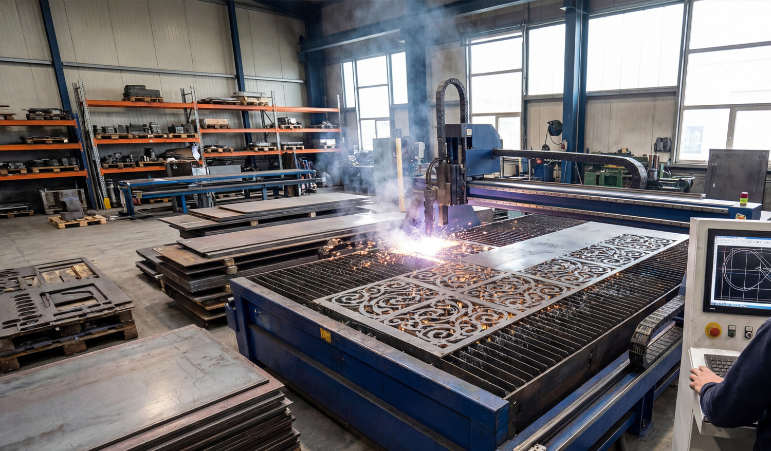
How to Handle Large DXF Files for CNC Cutting: Tips and Tricks
Handling large DXF files for CNC cutting is all about keeping performance under control—optimizing geometry, splitting smartly when needed, and setting up your software and hardware so big jobs run smoothly instead of crashing or freezing. Why Large DXF Files Are a Challenge in CNC Cutting Big DXF files usually mean one of three things: huge physical size, extreme detail, or a lot of different parts packed into one drawing. All of these can stress your CAD, CAM, and CNC controller. Slow performance: Viewers and CAM software can lag or freeze when panning and zooming. Long toolpath generation: CAM needs more time and memory to calculate toolpaths. Controller limits: Some machines cannot handle very large G-code files smoothly. Higher risk of errors: Corrupted saves, incomplete cuts, or lost steps mid-job. The good news: with the right workflow, you can make large DXF files much more manageable. Tip 1: Start by Cleaning the Geometry Even before you worry about file size, make sure the geometry in your large DXF is clean and reliable. Remove duplicates: Delete overlapping lines and curves to avoid double cuts. Close open contours: Ensure outer profiles and internal cutouts form closed loops. Delete stray entities: Get rid of tiny line fragments, points, and unused blocks. Unify polylines: Convert many small segments into longer polylines wherever possible. Clean geometry reduces toolpath complexity and helps CAM software handle the file more efficiently. Tip 2: Reduce Node Count on Very Detailed Artwork One of the biggest causes of “heavy” DXF files is excessive node count—especially from auto-traced images or intricate art. Use simplify curve or optimize functions in your CAD/vector software. Set a reasonable tolerance so curves stay visually accurate but use fewer points. Focus on high-density areas: decorative borders, textures, or traced logos. Replace jagged polylines with smoother arcs and splines where appropriate. Fewer nodes mean lighter DXF files, faster toolpaths, and smoother motion on the CNC machine. Tip 3: Break Huge Designs into Logical Sections Instead of trying to run one giant DXF for everything, split the design into smaller, logical pieces. By physical area: Divide large wall art or panels into tiles that fit your machine bed. By part type: Separate brackets, gussets, signs, and decorative pieces into different files. By operation: Use one DXF for cutting and another for engraving if complexity is high. This approach keeps individual files lighter and easier for your software and controller to handle. Tip 4: Use Layers to Organize Complex DXF Files Layers are essential when working with large, multi-part DXF drawings. Create layers for CUT_OUTSIDE, CUT_INSIDE, ENGRAVE, SCORE, and REFERENCE. Group similar parts or repeated components into named layers. Temporarily hide layers you are not working on to improve performance. Export layer-based subsets as smaller DXFs when you only need part of the design. Well-structured layers turn one huge DXF into a set of controllable chunks that are easier to process. Tip 5: Match DXF Detail Level to Your CNC Process Not all detail is useful in real cutting. What looks beautiful on-screen may be impossible or unnecessary on the machine. For laser cutting, you can keep fairly fine detail but still avoid micro cuts smaller than your kerf. For plasma cutting, simplify tiny shapes and thin bridges that will not hold up in metal. For routers and mills, respect tool diameter—remove features your bit cannot physically reach. Reducing detail that the machine cannot realistically reproduce shrinks file size and improves cut quality. Tip 6: Use Tiling for Oversized Panels If your DXF describes a large panel or mural that exceeds your machine’s cutting area, use tiling instead of forcing one massive file. Divide the design into tiles that fit safely inside your working envelope. Add small registration marks on each tile for accurate alignment during assembly. Export each tile as its own DXF or job file for easier toolpath generation. Tiling lets you cut very large installations in manageable sections without overloading your software or controller. Tip 7: Choose the Right DXF Version Some CAM and controller software works better with older, simpler DXF versions. Try exporting in R12/R14 DXF format, which is widely supported and less “heavy.” Avoid unnecessary entities (hatches, embedded images, 3D data) when you only need 2D paths. If your software allows, strip non-essential data on export to keep files lean. Using a compatible, minimal DXF version can dramatically reduce load times for large designs. Tip 8: Upgrade Hardware Where It Matters Large DXF files demand more from your computer. Sometimes software is not the bottleneck—hardware is. More RAM: Helps CAD and CAM handle big designs and long toolpaths. Fast SSD storage: Speeds up file loading, saving, and swapping large projects. Decent CPU: CAM calculations and simulations run faster with a stronger processor. If you regularly work with huge files, a modest hardware upgrade can pay off in reduced wait times and fewer crashes. Tip 9: Manage Toolpaths Smartly in CAM When generating toolpaths from large DXF files, be intentional about how you structure the job. Generate separate toolpaths for different areas or part groups instead of one mega-path. Use cut order controls to minimize rapid moves and reduce time. Consider breaking the job into multiple G-code files or job files if your controller has size limits. Simulate your paths to catch inefficient zig-zags and unnecessary passes. Well-organized toolpaths keep your CNC running efficiently, even when the source DXF is large. Tip 10: Compress and Archive Large DXF Projects Properly When you are done designing and cutting, store large DXF projects in a way that is safe and easy to retrieve. Use ZIP archives to compress related DXF, CAM, and preview files into one package. Include readme or notes with material, thickness, and machine settings that worked well. Organize archives by project, category, or customer so you can find them quickly later. Good archiving keeps your large, complex jobs from becoming a mess of random files that no one wants to touch again. Quick Checklist for Handling Large DXF Files Before sending a big DXF job to your CNC machine, run through this checklist: ✔ Geometry is clean (no duplicates, no gaps, no stray junk). ✔ Curves are simplified with a reasonable node count. ✔ Layers are organized into cut/engrave/score/reference. ✔ File is split or tiled if it exceeds machine limits. ✔ DXF version is compatible and does not include unnecessary entities. ✔ CAM toolpaths are grouped logically and have been simulated. ✔ A test cut has verified that detail and fits are correct. Conclusion Large DXF files do not have to be a headache for CNC cutting. By cleaning geometry, reducing node count, organizing layers, splitting oversized designs into tiles, and generating smart toolpaths, you can handle big, complex projects with confidence. Combine these tips with solid hardware and a consistent file management strategy, and your CNC laser, plasma, router, or mill will be ready to tackle large DXF jobs smoothly and reliably.

