CNC & DXF Design Guides
CNC & DXF Design Guides
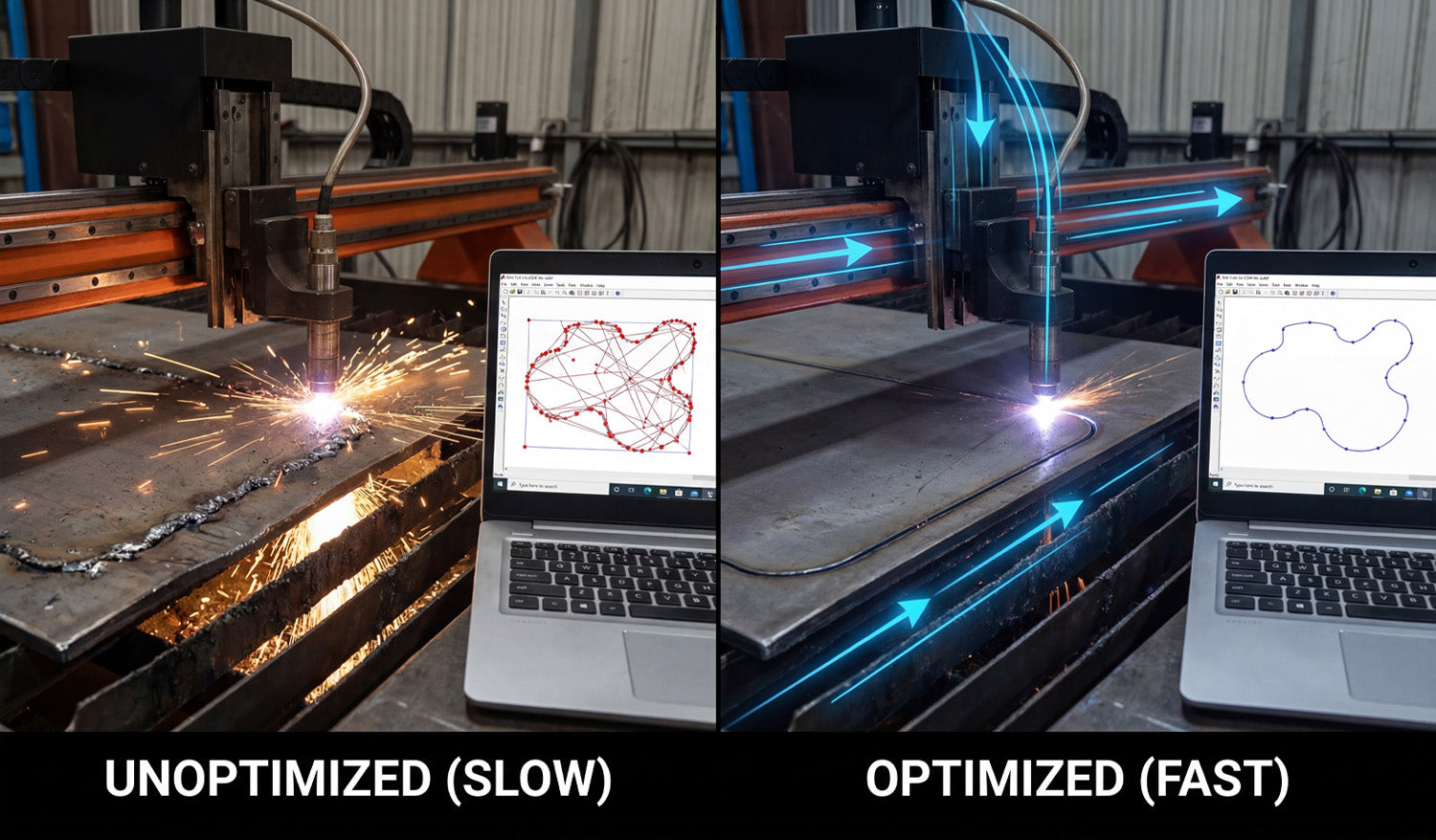
How to Speed Up Your CNC Cutting with Optimized DXF Files
Optimizing your DXF files is one of the easiest ways to speed up your CNC cutting, reduce cycle times, and get more parts done without buying a new machine. Why Optimized DXF Files Make CNC Cutting Faster Most people think faster CNC cutting means turning up speed or power. In reality, your DXF file has just as much impact. Every extra node, duplicate line, and unnecessary pierce adds time to the job. A clean, optimized DXF file helps your laser, plasma, router, or water-jet move smoothly and efficiently. By improving the geometry before you generate toolpaths, you can: Shorten total cutting time per sheet or part. Reduce pierce counts and direction changes. Get smoother motion and better edge quality at higher speeds. Fit more parts into each nesting layout. 1. Remove Duplicate and Overlapping Geometry Duplicate lines are one of the biggest hidden time-wasters in CNC cutting. If two lines sit on top of each other, the machine will often cut the same path twice. Use “delete duplicates” tools in your CAD software if available. Zoom in on corners and tight areas to look for stacked borders or overlapping outlines. Keep one clean outline for each contour and delete the rest. Fewer unnecessary tool passes mean less heat, less wear on consumables, and faster jobs. 2. Close Open Paths and Fix Gaps Open paths slow down your CAM workflow and can force you into manual fixes that eat up time. Turn on endpoint snaps and join dangling line ends. Use “close path” or “join” commands to create true closed loops. Replace messy corners with fresh lines or arcs if the gap is hard to repair cleanly. When all profiles are closed, your CAM software can assign inside and outside cuts automatically, speeding up setup and reducing errors. 3. Reduce Excessive Nodes for Smoother Motion Highly detailed curves made from thousands of tiny segments cause the machine to constantly slow down and speed up. That kills cutting speed and edge quality. Use a simplify or optimize curve function to reduce node count. Keep enough points to preserve the shape, but remove micro segments that add no real detail. Convert “stair-stepped” curves from traced images into smooth arcs or splines when possible. Smoother geometry lets the CNC machine maintain consistent velocity and handle higher feed rates with less vibration. 4. Design Continuous Contours to Cut More in One Pass Every time the cutting head lifts, retracts, and moves to a new start point, you lose time. Optimized DXF files minimize these non-cutting moves by using continuous contours where possible. Combine small segments into single polylines instead of separate objects. When appropriate, connect adjacent shapes with small bridges or shared lines to reduce pierces. For patterns and panels, consider common-line cutting where two parts share a cut, if your process and tolerances allow it. Fewer pierces and longer continuous cuts significantly reduce cycle time on both laser and plasma systems. 5. Simplify Detail to Match Your Machine and Material Sometimes the fastest way to speed up CNC cutting is to remove detail that the machine cannot cut efficiently anyway. Eliminate micro details that are smaller than your kerf or tool diameter. Thicken fragile bridges and thin lines that slow the machine or burn away. Replace dense textures or tiny cutouts with cleaner, bolder shapes that still look good. Well-optimized DXF artwork keeps the visual impact but cuts faster, more reliably, and with fewer rejects. 6. Use Layers to Streamline Operations DXF files support layers (and often colors), which you can use to control how your CAM software processes the job. Put inside cuts on one layer and outside profiles on another. Separate engraving, marking, or scoring from full-depth cuts. Use a reference layer for dimensions and notes that should never be cut. When you import an organized DXF, you can map entire layers to specific speeds, powers, and cut orders in just a few clicks, shortening setup time for every job. 7. Optimize Part Layout and Nesting in the DXF Stage Nesting is usually handled in CAM or nesting software, but your DXF design choices can make nesting faster and more efficient. Design parts with simple, nest-friendly outer profiles that pack well together. Avoid large, awkward outlines when a more compact shape would work just as well. Consider using tab locations that allow parts to share edges or nest tightly. Better nest layouts mean less head travel, fewer pierces, less scrap, and shorter total cut times per sheet. 8. Create Machine-Specific DXF Variants If you run multiple CNC machines (laser, plasma, router), a single DXF may not be ideal for all of them. Creating machine-specific variants helps you run each job at top speed. For laser, keep fine detail but clean up tiny gaps and islands that slow motion. For plasma, remove very fine details that the kerf cannot hold and widen narrow bridges. For router, adjust inside corners and pockets for the bit diameter, and remove unnecessary small features. Saving tuned versions (for example, design_laser.dxf, design_plasma.dxf) lets each machine cut faster without compromising quality. 9. Standardize Lead-Ins, Tabs, and Cut Order While lead-ins, tabs, and cut order are usually set in CAM software, your DXF preparation can support those decisions. Keep outlines clean and well separated so CAM can place lead-ins automatically in safe areas. Avoid overlapping contours that confuse inside/outside detection and slow you down during setup. Design parts so inner features are clearly recognized, making it easy to cut them before the outer profile. A DXF file that works with, not against, your CAM rules makes every job quicker to program and safer to run at higher speeds. 10. Build and Reuse a Library of Proven, Optimized DXF Files The biggest time savings come when you can reuse designs that are already optimized and tested. Save cleaned, optimized DXF files as “final” or “production-ready” versions. Store notes on best cutting speeds and settings alongside each design. Organize your library so you can quickly find and repeat jobs that you know cut fast and clean. Over time, your optimized DXF library becomes a real asset: every time you reuse a design, you benefit again from the time you spent optimizing it once. Quick Checklist: Is Your DXF Optimized for Speed? Before you send a job to your CNC machine, run through this fast checklist: All shapes are closed, with no gaps. No duplicate lines or overlapping outlines. Curves have a reasonable node count and are smooth. Detail level matches kerf and material strength. Layers clearly separate cut types and operations. Part outlines are nest-friendly for your sheet size. Machine-specific needs (laser, plasma, router) are considered. Conclusion Speeding up your CNC cutting is not just about pushing the machine harder—it starts with optimized DXF files. By cleaning geometry, reducing nodes, designing continuous contours, matching detail to your process, organizing layers, and building a library of proven designs, you can cut faster and smarter on any CNC system. The result is shorter cycle times, less wear on equipment, and more profitable jobs from the same machines you already own.
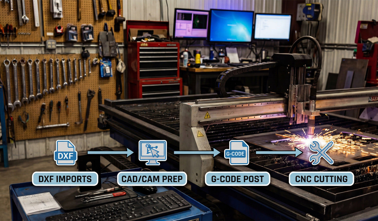
CNC Cutting for Beginners: Getting Started with DXF Files
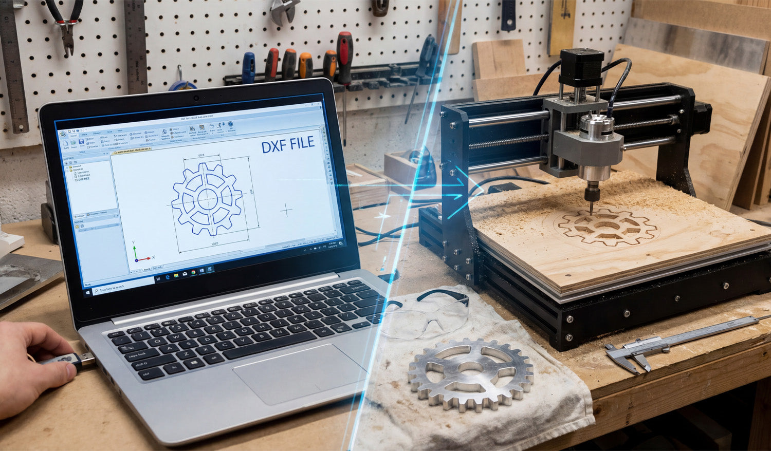
CNC cutting for beginners does not have to be scary. With a few basic skills and clean DXF files, you can go from simple ideas on your laptop to real parts made from metal, wood, or acrylic. What Is CNC Cutting? CNC (Computer Numerical Control) cutting means using a computer-controlled machine to cut shapes out of flat material. Instead of cutting by hand, you load a design into software, set your cutting settings, and let the machine follow the path automatically. Common CNC cutting machines include: Laser cutters: Great for thin wood, MDF, acrylic, leather, and engraving. Plasma cutters: Best for steel, stainless steel, and aluminum plates. CNC routers: Ideal for wood, plastics, foams, and some metals. Water-jet cutters: Used for stone, glass, composites, and thick metals. What Are DXF Files? DXF stands for Drawing Exchange Format. It is a 2D vector file type that stores lines, arcs, and curves as precise geometry instead of pixels. In simple terms, a DXF file is a digital blueprint that tells your CNC machine where to move and what to cut. DXF files are popular because: Most CAD and CAM software can open them. They are perfect for 2D cutting and engraving work. You can scale, edit, and reuse them without losing quality. How DXF Files Fit into the CNC Workflow For beginners, it helps to see the big picture from idea to finished part. The basic CNC cutting workflow looks like this: Design or download: You create a drawing or download a DXF file. Import into CAM software: You open the DXF and set up toolpaths (how the machine will cut). Set cutting parameters: You choose speed, power, pierce settings, or feeds and speeds. Simulate: You preview the cut on screen to make sure everything looks correct. Cut on the machine: You send the job to your CNC machine and cut the part from your chosen material. The DXF file is the bridge between your design idea and the real CNC machine. Where Beginners Can Get DXF Files You do not have to draw everything from scratch when you are just starting out. There are a few easy ways to get DXF files: Free DXF libraries: Many websites offer free DXF files so you can test your machine and learn the workflow. Paid design bundles: Larger DXF collections that are ready for commercial use and give you hundreds or thousands of designs. Simple own designs: You can draw basic shapes like brackets, signs, or panels in basic CAD software and export them as DXF. Starting with clean, cut-ready DXF files lets you focus on learning the machine instead of fighting with drawings. Step-by-Step: Your First CNC Cutting Project with DXF Files Step 1: Choose a Simple Design Pick a small project like a basic sign, a simple wall art shape, or a bracket. Avoid extremely fine detail and tiny text for your first cuts. Make sure the design fits easily inside your machine’s working area. Step 2: Open the DXF File in Your Software Open your CAD or CAM software and use the Import or Open command. Load the DXF file and check that it appears at a reasonable size on the screen. Switch to an outline or wireframe view so you see only the paths your machine will follow. Step 3: Check the Scale and Units Use a measure tool to check the overall width and height of the design. Confirm the file is in the correct units (millimeters or inches). If the part is too large or too small, use the scale command to adjust it before you continue. Step 4: Look for Basic Geometry Problems Even beginners can spot and fix the most common DXF issues: Open paths: Make sure outlines are closed loops, not almost-closed shapes with small gaps. Duplicate lines: Delete any lines that sit exactly on top of each other to avoid double cuts. Stray points: Remove tiny dots or segments that serve no purpose. Step 5: Assign Toolpaths in CAM Software Tell the software which paths are outside cuts, inside cuts, and engraving (if any). Set cutting direction and order. A good rule is to cut inner shapes and holes first, then the outer perimeter last. Apply kerf compensation so the machine cuts slightly off the line to achieve true final dimensions. Step 6: Choose Cutting Settings for Your Material Your machine manual or community forum is a good place to start for basic settings. For beginners: Use conservative speeds and power levels until you understand how your machine behaves. Write down settings that work well, including material type, thickness, speed, power, and gas or air if applicable. Remember that each machine and material combination may require different settings. Step 7: Run a Simulation Most CAM software can simulate the cut on screen. Watch for unexpected jumps, strange toolpaths, or missed shapes. If something looks wrong, go back and fix the DXF or toolpaths before going to the machine. Step 8: Cut a Test Piece on Scrap Material Always test your first design on scrap material, not expensive or final stock. Stay near the machine and watch how it cuts. Look at the arc or beam, listen for unusual sounds. After the cut, check fit, edge quality, and detail. Adjust settings and toolpaths as needed. Safety Basics for CNC Cutting Beginners CNC cutting uses high power tools, hot sparks, and moving parts. Even small machines deserve respect. Wear appropriate eye and hearing protection. Use gloves and proper clothing when handling sharp material, but follow your machine’s safety rules about clothing near moving parts. Keep your work area clean and free of loose items. Know how to stop the machine quickly in an emergency. Never leave the machine unattended while it is cutting, especially during your early learning phase. Common Mistakes Beginners Make with DXF Files Knowing the typical beginner mistakes makes them easier to avoid: Using random images as DXF: Regular JPG or PNG images must be converted to vector paths before cutting. Forgetting to check size: Cutting a design only to discover it is much smaller or larger than expected. Too much detail: Very thin lines and tiny gaps that look good on screen but fail in real materials. No test cuts: Going straight to final material without testing settings first. Poor file organization: Saving everything as “new.dxf” and losing track of which design actually worked. Tips for Growing Your CNC Skills with DXF Files Start with simple, proven DXF designs and focus on mastering your machine settings. Keep a notebook or digital log of what settings worked for each material and thickness. Gradually move to more detailed projects once you feel comfortable with basic shapes. Try editing existing DXF files to learn how geometry, layers, and scaling affect the final cut. Build your own organized DXF library so you can quickly repeat successful jobs or offer them as products. Conclusion CNC cutting for beginners is much easier when you understand the role of DXF files and follow a simple, repeatable workflow. By starting with clean designs, checking scale and geometry, assigning toolpaths carefully, and always testing on scrap material, you can quickly gain confidence with your CNC laser, plasma, or router. Over time, your DXF library and your skills will grow together, turning basic digital drawings into real, accurate parts and creative products.
How to Organize Your DXF Files for Efficient CNC Cutting
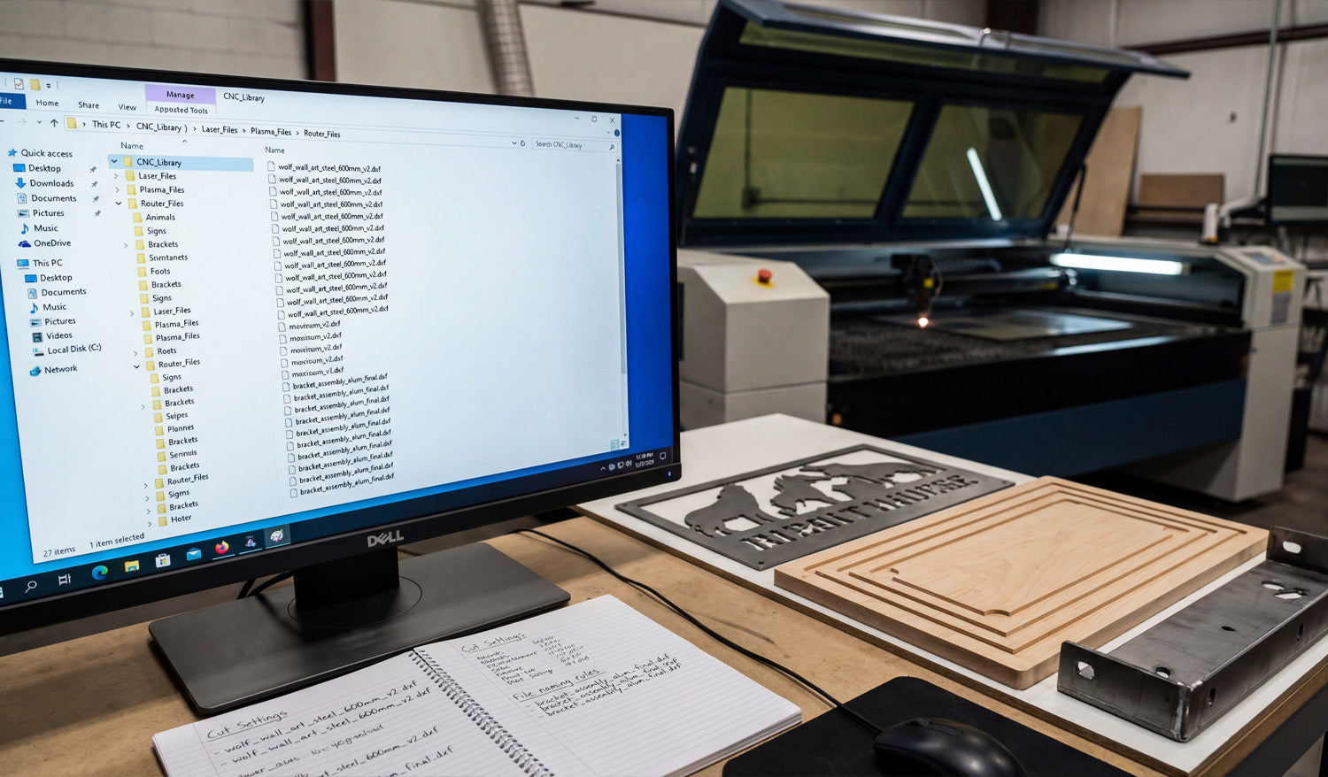
Organizing your DXF files properly is one of the easiest ways to speed up CNC cutting, avoid mistakes, and keep your shop running efficiently as your design library grows. Why DXF File Organization Matters for CNC Cutting In a real CNC workflow, the problem is rarely “I do not have a design.” It is usually “I cannot find the right design, the latest version, or the file that was already tested.” Poor organization costs time, creates wrong cuts, and makes training new operators harder. A clear DXF organization system helps you: Find proven designs quickly when an order comes in. Know which files are ready for production and which are still prototypes. Keep master artwork safe while using copies on the shop floor. Share files across laser, plasma, router, or water-jet machines without confusion. Step 1: Build a Logical Folder Structure Start by creating a folder structure that matches the way you actually work. Keep it simple and scalable. Common ways to organize DXF files: By product category: Animals, signs, panels, brackets, logos, letters, etc. By material or thickness: Steel-3mm, Steel-6mm, Stainless-2mm, MDF-18mm. By machine type: Laser, Plasma, Router, Waterjet. By client or project: ClientName / ProjectName / DXF. You can combine ideas, for example: CNC_Library / Laser / Wall_Art / Animals CNC_Library / Plasma / Brackets / Steel_6mm As long as the structure is consistent and easy to understand, it will help everyone in the shop find what they need. Step 2: Use Clear, Consistent File Names Good file names are just as important as good folders. They should tell you what the design is without opening it. Useful elements to include in a DXF file name: Product type or category: wolf_wall_art, round_sign, L_bracket. Material or thickness (optional): steel_3mm, MDF_18mm. Size or main dimension: 600mm, 24inch. Version: v1, v2, final. Example naming patterns: wolf_wall_art_steel_3mm_600mm_v2.dxf house_number_sign_MDF_18mm_400mm_final.dxf Staying consistent makes it much easier to sort, search, and recognize designs at a glance. Step 3: Separate Master Designs from Production Files Your original “master” design should not live in the same place as everyday production files. Keeping them together is a common source of accidental edits and lost work. Create a Master folder for original, fully editable designs (CAD, AI, SVG, etc.). Create a Production folder for cut-ready DXF files and machine-specific versions. Never overwrite master files with quick edits from the shop floor. This separation protects your design assets and keeps production workflows clean and focused. Step 4: Store Related Files Together A DXF file is only one piece of a full CNC job. You may also have: Preview images (JPG/PNG) for quick visual reference. CAM files or post-processed G-code for specific machines. Notes about tested settings (power, speed, pierce, feeds, speeds). License or usage information if the design came from an external library. To stay organized, group related files inside a single folder per design or per product: wolf_wall_art / master_design.ai wolf_wall_art / wolf_wall_art_steel_3mm_600mm.dxf wolf_wall_art / wolf_wall_art_preview_600mm.png wolf_wall_art / notes_cut_settings.txt Step 5: Use Version Control for Changes Designs evolve. Holes move, sizes change, customers request adjustments. Without version control, it is easy to lose track of which DXF is the correct one. Add v1, v2, v3 or date stamps to file names when making changes. Keep a short CHANGELOG.txt or note file in each design folder summarizing what changed and why. Mark stable designs as _final once they are fully tested and approved. Even a simple manual version system is better than guessing which file “should” be right before a rush job. Step 6: Create “Ready-to-Cut” Folders for the Shop Floor Operators on the shop floor should not have to dig through old drafts or half-finished experiments. Make their life easier with a clear “ready-to-cut” structure. Create a top-level folder like Ready_To_Cut or Production_Files. Inside, create folders by machine: Laser, Plasma, Router. Only place tested, approved DXF files in those folders. This way, when an operator opens the Laser / Ready_To_Cut folder, every design they see has already passed your quality check. Step 7: Use an Index or Catalog for Your DXF Library As your library grows, even a good folder structure may not be enough. Creating a central index helps you see the “big picture.” You can use a simple spreadsheet or database that tracks: Design name and category. File path or folder location. Available sizes and materials. Machine compatibility (laser, plasma, router). Notes on tested settings and best-selling variations. This catalog becomes a powerful tool when you want to plan new product lines, quote jobs, or decide which designs to promote. Step 8: Tag Files with Metadata Where Possible On many operating systems, you can add tags or comments to files. While not as important as folders and names, metadata is helpful for quick search. Add tags like “animal, wall art, 600mm, steel” to your DXF or preview files. Use consistent keywords for materials, sizes, and styles. Search by tag when you need a certain type of design for a new product idea. If your system does not support tags well, stick to consistent naming and a separate spreadsheet index. Step 9: Back Up and Sync Your DXF Library DXF files and design assets are a core part of your business. Losing them can be more painful than losing a single machine. Regularly back up your entire CNC_Library folder to an external drive or cloud storage. Use at least one off-site backup to protect against hardware failure or local disasters. Test your backup occasionally by restoring a few sample designs and opening them. A strong backup strategy ensures your organized library remains safe for years to come. Step 10: Document Your System and Train Your Team The best organization system only works if everyone follows it. Take a few minutes to document your structure and rules. Write a short guide: how to name files, where to save new designs, how to mark files as “final.” Show new staff where to find Master versus Ready-To-Cut files. Review the system occasionally and adjust it if your shop’s needs change. Consistency over time is what turns a folder tree into a true CNC design library. Common DXF Organization Mistakes to Avoid Storing everything on the desktop: Hard to back up and impossible to scale. Using names like “new.dxf” or “test.dxf”: No one knows what they are later. Mixing master and production files: Increases the risk of overwriting critical designs. No backup plan: A single hard-drive failure can wipe out years of work. Changing rules every month: Pick a structure and stick with it unless you have a clear reason to change. Conclusion Organizing your DXF files for efficient CNC cutting is not about fancy software—it is about simple, consistent habits. With a logical folder structure, clear file names, separate master and production files, a central index, and solid backups, you turn scattered designs into a reliable CNC library. That means faster setup, fewer errors, easier training, and a smoother path from digital artwork to finished parts on every machine in your shop.

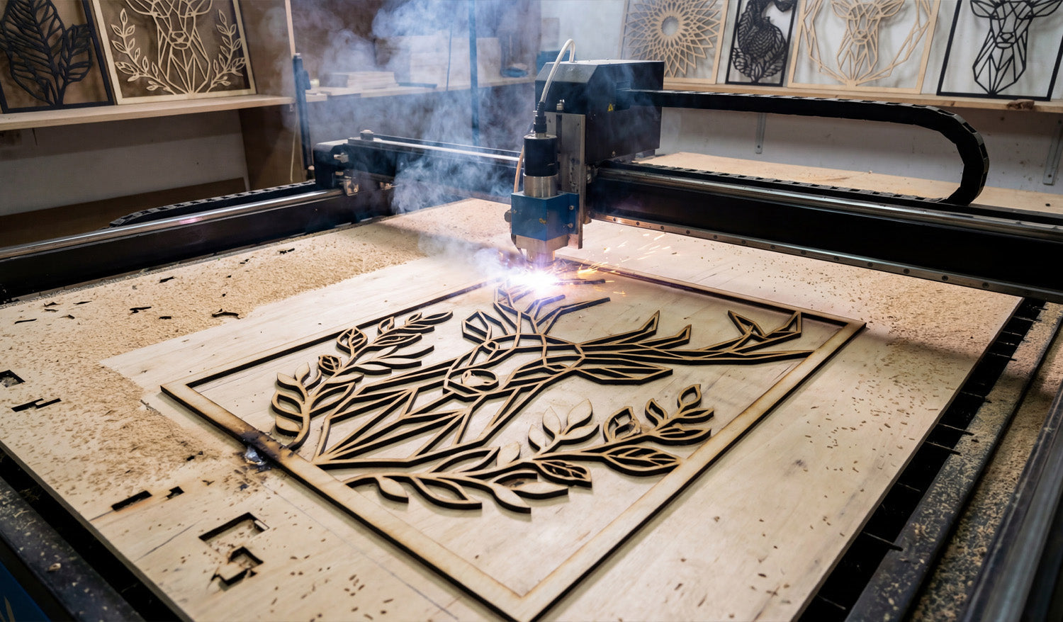
Why DXF Files Are Ideal for Detailed CNC Projects
DXF files are ideal for detailed CNC projects because they store precise vector geometry, handle complex shapes, and work reliably across most CAD, CAM, and CNC systems. What Makes a CNC Project “Detailed”? Not all CNC jobs are simple rectangles and bolt holes. Many real projects include: Fine decorative patterns and filigree. Intricate metal art and wall panels. Logos, lettering, and monograms. Complex slot-and-tab assemblies. Multi-part layouts with many small features. These detailed CNC projects demand clean geometry, stable scaling, and accurate toolpaths. That is exactly where DXF files shine. Vector-Based Geometry for Sharp Detail DXF files store shapes as vectors—lines, arcs, and curves defined by math, not pixels. This has several benefits for detailed CNC work: Infinite zoom: You can zoom in on tiny areas without losing clarity or introducing blur. Smooth curves: Arcs and splines produce flowing motion on the machine instead of jagged, stair-stepped edges. Precise control: You can define exact radii, angles, and distances for every element of the design. For intricate signs, patterns, and artwork, this vector foundation is essential to keep detail crisp and accurate. Excellent Support Across CNC Software and Machines DXF is one of the most widely supported formats in the CNC world. This is especially important for detailed projects, which often move through multiple tools and workflows. Design tools: Most CAD and vector programs can open, edit, and save DXF files. CAM systems: Laser, plasma, router, and water-jet CAM software almost always support DXF import. Machine controllers: Many controllers or their companion tools read DXF directly or through a simple conversion step. When you work with complex detail, you do not want to redraw your design just to switch software or machines. DXF lets you keep a single, consistent design file across your entire workflow. Layers and Colors for Organizing Complex Operations Detailed CNC projects often require more than one kind of operation. DXF files support layers and, in many systems, colors that can be mapped to different tasks. Use one layer for outer profiles, another for inner cutouts. Place engraving, scoring, or marking on separate layers. Keep construction lines, guidelines, and notes on a non-cutting layer you can hide later. This structure makes it much easier to manage detailed designs with thousands of elements. You can quickly turn operations on or off, adjust settings layer by layer, and avoid mistakes during setup. Clean Scaling Without Losing Detail Because DXF files are vector-based, they scale up or down without becoming blurry or blocky. For detailed CNC projects, that means: You can create multiple size versions of the same design (small, medium, large) from the same DXF. Logos and artwork stay sharp even when resized for different products. You can adapt one design to different machines and sheet sizes by scaling it appropriately. The key is to check minimum feature sizes after scaling. As long as your smallest bridges, gaps, and text remain above your machine’s cutting limit, DXF handles detail very well at varying scales. Better Toolpath Generation for Intricate Shapes CAM software can generate much better toolpaths when it receives clean DXF geometry. This is especially important for projects with many small curves, corners, and internal cutouts. Stable motion: Smooth DXF curves translate into steady movement, which improves edge quality. Smarter ordering: CAM tools can easily cut inner features first, then outer profiles, to protect fine details. Controlled kerf compensation: With predictable geometry, you can apply kerf offsets and still keep delicate shapes accurate. For detailed metal art or technical parts, this combination of clean input and intelligent toolpaths is crucial for success. Easy Editing and Iteration for Complex Designs Detailed CNC projects rarely stay the same forever. Customers want changes, dimensions shift, and you may want to refine the design for faster cutting. DXF files make these adjustments easier. You can edit individual nodes and curves without redrawing the entire part. You can add or remove detail in specific areas while keeping the rest of the design intact. You can use boolean tools (union, subtract, intersect) to merge or modify complex shapes. Instead of starting from scratch, you can keep improving your DXF over time and build a richer, more refined library of detailed designs. Reliable Reuse for Product Lines and Repeat Jobs Once you have a detailed DXF design that cuts well, it becomes a reusable asset. Use the same design across different materials (steel, stainless, aluminum, wood, acrylic). Offer multiple versions of a product line simply by adjusting size and thickness in your CAM setup. Run repeat orders with confidence, knowing the design has already been tested and optimized. Over time, a library of proven DXF files for detailed CNC projects can become a major competitive advantage for your shop or brand. Handling High Detail on Different CNC Machines Laser Cutting Lasers are ideal for fine detail, and DXF geometry lets them follow extremely tight paths. DXF-based designs help you dial in power and speed while keeping delicate areas intact. Plasma Cutting Plasma has a wider kerf, but a good DXF lets you manage detail within those limits. By controlling minimum feature size in your DXF, you can still achieve impressive detail in metal art and signs. CNC Routers Routers rely on bit diameter; DXF files allow you to design corners, pockets, and contours that respect tool size. Detailed inlays, signs, and 2.5D carvings all benefit from precise DXF geometry. Tips for Getting the Most Detail from DXF Files Start with clean vectors: Avoid auto-traced artwork that is noisy or overloaded with nodes. Design with real kerf in mind: Make sure your smallest elements are larger than your tool width. Test cut small sections: Try a portion of your detailed design on scrap material before running a full sheet. Optimize curves: Simplify excessive nodes for smoother machine motion without losing important shape. Organize layers: Use layers for different detail levels, like fine engrave paths versus full-depth cuts. Conclusion DXF files are ideal for detailed CNC projects because they combine precise vector geometry, strong software support, layer-based organization, and easy scalability. Whether you are cutting intricate metal art, branded signage, or complex mechanical parts, a well-prepared DXF file gives your CNC machine the clear instructions it needs to reproduce even the smallest details with confidence. By designing, organizing, and testing your DXF files carefully, you unlock the full potential of detailed CNC work on laser, plasma, router, and other cutting systems.
Creating Precise CNC Designs with DXF Files: A Step-by-Step Guide
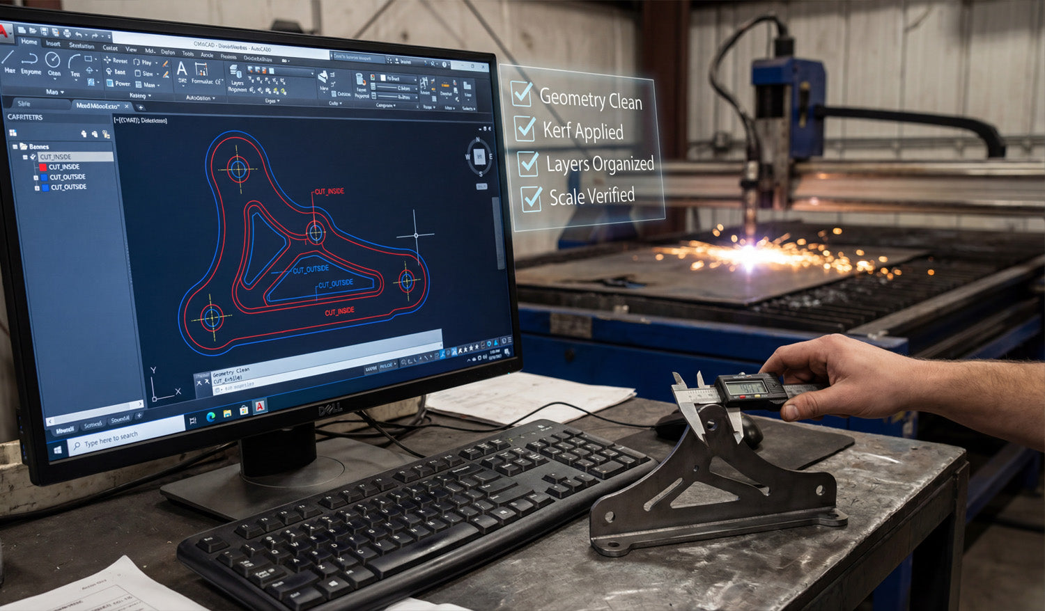
Precise CNC designs start with clean DXF files; this step-by-step guide walks you through planning, drawing, checking, and preparing your files for reliable cutting. Why Precision in DXF Design Matters for CNC Cutting Every CNC cut is only as accurate as the design behind it. If your DXF file has sloppy dimensions, open paths, or random geometry, your laser, plasma, router, or water-jet will simply reproduce those errors in steel, wood, or acrylic. A precise DXF file, on the other hand, gives you: Cleaner edges with less grinding or sanding. Better fit between parts, tabs, slots, and bolt holes. Reduced scrap because you catch mistakes before cutting. Repeatable results for production runs and reorders. The process below shows how to create precise CNC designs with DXF files from the very first sketch all the way to export. Step 1: Define the Purpose and Requirements of Your Design Before you open any software, be clear about what you are designing and how it will be used. What is the part? Metal art, a bracket, a sign, a furniture component, a panel? What material? Mild steel, stainless, aluminum, plywood, MDF, acrylic, or something else? What thickness? Material thickness affects minimum hole size, bridge width, and tab strength. What tolerances? Does it need to be decorative only, or does it have to fit tightly with other parts? Which machine? Laser, plasma, router, or water-jet, and what is the bed size? These answers influence your minimum feature sizes, the amount of detail you can safely include, and the overall dimensions you should target. Step 2: Set Up Your CAD Drawing Correctly A precise DXF file starts with a clean drawing environment in your CAD or vector software. Choose units: Decide whether you will work in millimeters or inches and stick to it throughout the project. Set grid and snaps: Turn on grid, endpoint, and midpoint snaps to keep geometry aligned and clean. Create basic layers: For example, use layers like CUT_OUTSIDE, CUT_INSIDE, ENGRAVE, and REFERENCE. Set line weights and colors: Even if the machine ignores line weight, colors and layers help you keep the file organized. Step 3: Draw the Base Geometry with Accuracy in Mind Now you can start drawing the actual shapes of your CNC part or artwork. Use lines, arcs, and polylines instead of many tiny segments. Rely on dimensions and constraints where available, instead of “eyeballing” lengths and angles. Draw important reference geometry (like bolt circles, center lines, or bounding boxes) on a separate reference layer. For decorative designs, keep key shapes snapped to known points to avoid micro-gaps. Take your time on this step. The more accurate your base drawing is, the less cleanup you will need later. Step 4: Add Dimensions, Constraints, and Relationships Precision is not just about drawing; it is about controlling how geometry behaves when you edit or rescale it. Apply dimensions to critical features such as hole diameters, slot widths, and overall height/width. Use constraints (horizontal, vertical, parallel, perpendicular, concentric) to keep geometry aligned. Lock key reference dimensions so accidental drags do not distort the design. By constraining your sketch, you can adjust one or two main dimensions without breaking the entire design. Step 5: Design for Kerf, Tool Diameter, and Material Limits Real CNC machines remove material with a finite tool width (laser kerf, plasma kerf, or cutter diameter). Very fine details that look good on screen may disappear or break in real life. Kerf compensation: Plan for the cut width so inside and outside dimensions come out correctly. Minimum feature size: Make sure the smallest bridges and gaps are larger than your kerf and strong enough for the material. Corner radii: For routers, inside corners will always be rounded by the bit diameter. Design slots and pockets accordingly. Text and logos: Avoid ultra-thin fonts; choose styles and sizes that remain readable after cutting. Step 6: Close All Paths and Clean Up the Geometry Before you export to DXF, your geometry should be clean, closed, and free from errors. Close shapes: Ensure all cut profiles (outer borders and inner holes) are fully closed loops. Remove duplicates: Delete overlapping lines or stacked shapes that cause double cuts. Simplify curves: Use “simplify” or “optimize” tools to reduce unnecessary nodes while keeping shapes smooth. Delete stray objects: Remove tiny islands, construction lines, or leftover marks you do not want to cut. Switch to an outline or wireframe view to see only curves and lines; this makes problems easier to spot. Step 7: Organize Layers for CNC Operations Organizing your layers pays off when you move into CAM or machine software. Assign outer profiles to one layer (for example, CUT_OUTSIDE). Assign inner holes and cutouts to another layer (for example, CUT_INSIDE). Put engraving, scoring, or marking on separate layers so they can be mapped to different power/speed settings. Keep non-cutting reference geometry on a layer you can easily turn off or exclude from export. This structure makes it simple to tell your CAM software which paths to cut first, which to engrave, and which to ignore. Step 8: Verify Scale and Add a Reference Dimension Before you export the DXF, confirm that your design is correctly sized. Measure the overall width and height of the part and key internal features. Compare those measurements to your original design requirements or customer drawing. Optionally add a small reference rectangle or line (for example, exactly 100 mm wide) to help verify scale in CAM software. If you later import this DXF into a different system, that reference value gives you a quick sanity check that units and scaling are correct. Step 9: Export the Design as a Clean DXF File Now you are ready to export. Use “Save As” or “Export” and choose DXF as the file type. Select a stable DXF version (often R12, R14, or a version your CAM software prefers). Turn off export of unnecessary items (like hatches or complex text) if they are not needed for cutting. Give the file a clear name that describes the part, material, and maybe size (for example, panel_bracket_6mm_steel.dxf). Step 10: Test the DXF in Your CAM or Controller Software Before you commit to production, test your exported DXF with the real CNC software. Import the DXF and check that layers map correctly to operations (cut, engrave, mark). Verify the measured size using the reference dimension or known features. Generate toolpaths and run a simulation to ensure the machine follows the intended routes. Cut a sample part on scrap material to verify fit, edge quality, and detail level. If something is off, go back to the CAD file, correct the issue, and export a new DXF. Precise designs often go through one or two small iterations before they are production-ready. Conclusion Creating precise CNC designs with DXF files is a step-by-step process: define your requirements, set up your drawing environment, draw with accuracy, design for real-world kerf and material limits, clean up geometry, organize layers, and verify scale before you export. When you follow these steps, your DXF files become reliable digital blueprints that any compatible CNC machine can turn into accurate, repeatable parts—saving you time, material, and headaches on every project.

How to Scale DXF Files for Different CNC Machines
Learning how to scale DXF files correctly for different CNC machines helps you avoid sizing mistakes, wasted material, and parts that simply do not fit. Why Scaling DXF Files Matters in CNC Work A DXF file is just a 2D blueprint, but every CNC machine has its own table size, units, and material limits. If the design is not scaled correctly, you may end up with a part that is too big for the machine, too small to be useful, or completely off from the drawing your customer approved. Good scaling practice makes it easy to: Move the same design between laser, plasma, and router machines. Create small, medium, and large versions of a product line. Match real-world dimensions and hole sizes accurately. Keep design proportions consistent across different materials and thicknesses. Step 1: Understand Units vs Scaling Before you scale anything, you need to know if the DXF file uses millimeters or inches. Many “scaling problems” are really just unit problems. Units problem: The file was drawn in inches but imported as millimeters (or the opposite), causing a 25.4x size error. Scaling problem: You intentionally want to make the design larger or smaller while keeping the same proportions. Always fix unit issues first, then perform intentional scaling. How to Check Units Quickly Import the DXF into your CAD or CAM software. Measure a known feature (for example, a 100 mm width specified by the designer). If the measurement is off by exactly 25.4x, you know you have an inches vs millimeters mismatch. Step 2: Decide the Final Size for Each Machine Different CNC machines have different working areas and sweet spots. Before scaling, answer these questions: What is the maximum cutting area? For example, 600×400 mm, 4×4 ft, or 4×8 ft. How much margin do you need? Leave a small border around the sheet to avoid hitting clamps or edges. What size does the customer or product require? For signs, panels, or art, you may have specific height or width targets. Once you know the final target size, you can calculate a clean scaling factor and apply it safely. Step 3: Use Uniform (Proportional) Scaling When you scale a DXF file, you almost always want to keep the same proportions in both directions. Choose a uniform scaling option so X and Y are multiplied by the same factor. Avoid stretching only in one axis unless you have a very specific reason to distort the design. Example: Scaling to Fit a 600 mm Wide Machine Measure the current width of the design in your CAD software (for example, 800 mm). Decide the new width (for example, 580 mm to leave a bit of margin on a 600 mm table). Calculate the scaling factor: 580 ÷ 800 = 0.725. Select all geometry and apply a uniform scale of 72.5% (factor 0.725). Re-measure the width to confirm it is now approximately 580 mm. Step 4: Consider Minimum Feature Sizes and Material Limits Scaling is not just about table size; it also affects hole diameters, bridge thicknesses, text readability, and material behavior. Small details: When you scale down, thin bridges and tiny gaps may become too fragile to cut. Holes and slots: Very small holes may close up due to kerf and heat, especially in plasma cutting. Text and logos: At small sizes, letters can burn away or blur together. After scaling, zoom in and check: Are the narrowest parts still wider than your kerf and strong enough for the material? Are hole sizes still functional for bolts, screws, or hardware? Is engraved or cut text still legible at the new size? Step 5: Scaling DXF Files for Different Machine Types Scaling for Laser Cutters Lasers can handle very fine details, but thin bridges in paper or thin wood can still burn away. When scaling down, consider slightly thickening critical lines and bridges in your CAD software. Double-check small internal shapes like letters “e, a, o” for readability at the new size. Scaling for Plasma Cutters Plasma has a wider kerf and more heat than lasers. A design that works at 600 mm tall may not work at 200 mm tall without adjusting detail. After scaling down, increase minimum slot and gap sizes so molten metal has room to escape. Scaling for CNC Routers Router bits have a fixed diameter, so inside corners and fine details round off. When scaling up, deeper cuts may require more passes or a stronger machine. Check small internal corners and pockets after scaling; some features may need to be redesigned for the tool size. Step 6: Use Reference Shapes to Verify Scale Across Machines A simple reference shape inside your DXF makes scaling and verification easier. Add a known-size rectangle or line (for example, 100 mm wide) next to your design. After importing into any CAM or controller software, measure that reference shape. If it reads correctly, you know the entire drawing scaled and imported correctly. This trick is especially helpful when moving designs between different brands of machines and software. Step 7: Save Machine-Specific Versions of Your DXF To keep your workflow organized, save separate versions of scaled files for each machine or product size. Use clear filenames like design-name_laser-400mm.dxf or panel-name_plasma-1200mm.dxf. Store these in folders by machine type or product line. Always keep a master DXF at the original size so you can create new variants later. Common Scaling Mistakes to Avoid Scaling text but not outlining it: Some systems change text appearance when you scale. Convert text to paths before final scaling. Forgetting to scale hole centers and fixtures: If you use separate construction geometry for fixtures, make sure it scales too. Only scaling in CAM: If you scale only at the CAM or controller level, it is easy to forget what size the “real” design is. It is often cleaner to scale in CAD and save a new DXF. Skipping test pieces: Always cut a small test piece after scaling, especially when you change machines or materials. Simple Scaling Workflow You Can Reuse Here is a quick, repeatable process for scaling DXF files for different CNC machines: Open the master DXF in your CAD software. Confirm units by measuring a known feature. Set target size based on machine bed and product requirements. Calculate scaling factor (new size ÷ old size). Apply uniform scaling to all geometry. Check minimum feature sizes for the target machine and material. Add or verify a reference dimension box (for example, 100 mm line). Save as a new DXF named for that machine or size. Import into CAM, verify size with the reference, and run a test cut. Conclusion Scaling DXF files for different CNC machines is not difficult once you understand units, target size, and the limits of each cutting process. By using uniform scaling, checking minimum feature sizes, adding reference shapes, and saving machine-specific versions of your designs, you can confidently move the same artwork between laser, plasma, router, and other CNC systems without nasty surprises. The result is more flexible production and a design library that truly works across your entire shop.
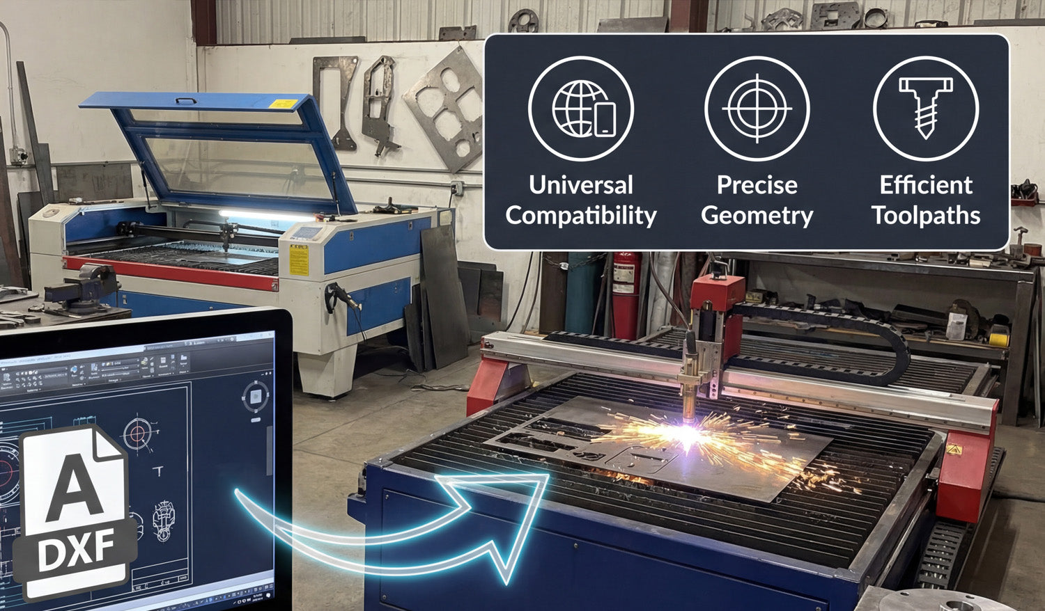
Exploring the Benefits of Using DXF Files for Laser and Plasma Cutting
Using DXF files for laser and plasma cutting gives you cleaner toolpaths, easier workflows, and more consistent results across different machines and materials. Why DXF Files Work So Well for Laser and Plasma Cutting Laser and plasma cutters both rely on precise 2D paths to move the beam or torch around your material. DXF (Drawing Exchange Format) files store those paths as vectors: lines, arcs, and curves defined by coordinates. That makes DXF a natural fit for any sheet-cutting process where accuracy, repeatability, and clean motion really matter. Instead of guessing from a pixel-based image, your machine reads exact geometry from the DXF and turns it into stable, efficient toolpaths. Benefit 1: Universal Compatibility Across CAD and CAM Software One of the biggest advantages of DXF is that almost every CAD, CAM, and CNC control program can read it. This helps you: Design anywhere: Create or edit your drawing in your favorite CAD or vector software. Cut on many systems: Import the same DXF into different laser or plasma CAM tools. Share with others: Send DXF files to customers, suppliers, or partner shops without worrying about software brands. For a busy laser or plasma shop, that compatibility means less time fighting file formats and more time actually cutting parts. Benefit 2: Clean Vector Geometry for Precise Cutting Laser and plasma cutters do their best work when they receive smooth, continuous curves and straight lines. DXF is built around exactly that kind of geometry. Smoother edges: Well-drawn DXF curves produce neat, flowing motion on the machine. Accurate shapes: True arcs and circles cut more consistently than shapes approximated from low-resolution images. Predictable kerf: Clean geometry makes it easier to apply kerf compensation and hit your final dimensions. Whether you are cutting detailed wall art or tight-tolerance brackets, DXF gives you a solid base for accurate results. Benefit 3: Faster, More Efficient Toolpaths When your input geometry is clean, your CAM software can generate better toolpaths for laser and plasma cutting. Reduced pierces: DXF files that use continuous contours allow the CAM system to combine segments and minimize pierce points. Optimized cut order: Inner shapes can be cut before outer profiles, reducing part movement and waste. Less machine “jitter”: Smooth paths keep the head or torch moving consistently, which improves edge quality and speed. Even small improvements in path efficiency can add up, especially when you are running many parts or large nests per day. Benefit 4: Easy Scaling and Reuse DXF files store vector geometry, which scales without losing quality. This is a big advantage for laser and plasma shops that need multiple sizes of the same design. Quickly create small, medium, and large versions of a sign or art piece by scaling the DXF. Reuse the same base file for different material thicknesses or product lines. Keep your design library simple by storing “master” DXFs and creating size variants as needed. This flexibility makes it easier to respond to custom requests and build product families around proven designs. Benefit 5: Better Nesting and Material Utilization Professional nesting software works best with clear, closed shapes—and that is exactly what a good DXF file provides. Tighter nests: Closed, non-overlapping DXF contours allow parts to be packed closely to reduce scrap. Accurate part outlines: Reliable geometry means fewer surprises when parts are removed from the sheet. Consistent margins: Known shapes make it easy to control edge distance and safe spacing between parts. For both laser and plasma cutting, better nesting translates into real savings on steel, aluminum, stainless, or other sheet materials. Benefit 6: One File Format for Both Laser and Plasma Many shops run both laser and plasma cutters, or move jobs between them depending on material and thickness. DXF files make this easy: Use the same design as a fine-detail laser job or a heavy-duty plasma job. Apply different kerf, speed, and power settings in CAM while keeping the DXF geometry identical. Shift production between machines without redrawing the part from scratch. This shared file format lets you match the process—laser or plasma—to the job while keeping your design workflow simple. Benefit 7: Clear Layer and Color Control for Operations DXF supports layers and colors, which many CAM systems use to assign different operations. Separate cut, engrave, mark, and etch paths on different layers. Map each color to a specific power and speed combination on your laser. For plasma, differentiate pierce-only, cut, and mark paths clearly in the DXF. Organized DXF files make it much harder to mix up operations, reducing setup time and costly mistakes on the machine. Benefit 8: Easier Collaboration and Outsourcing If you work with designers, customers, or outside cutting services, DXF is a simple, shared language. Designers can send you DXF files instead of proprietary CAD formats. You can outsource overflow work to other shops that accept DXF-based jobs. Customers can approve proofs and revisions based on the same file that will be cut. This makes your laser or plasma shop more flexible and able to handle larger projects without rebuilding the design from scratch for every partner. Benefit 9: Future-Proof Design Library Because DXF is so widely supported and long-lived, it is a safe choice for building a permanent design library. Old DXF files can still be opened and cut on new software and machines years later. You are less dependent on a single CAD brand or subscription to access your own designs. Your library of signs, art, brackets, and parts becomes a long-term asset for your business. As laser and plasma technology evolves, DXF support is almost guaranteed to remain a core feature in future systems. Conclusion DXF files offer a powerful combination of compatibility, precision, efficiency, and flexibility for both laser and plasma cutting. They help you create cleaner toolpaths, get better edge quality, reduce material waste, and reuse designs across different machines and materials. Whether you are a hobbyist, a small fab shop, or a growing production facility, building your workflow around well-prepared DXF files is one of the smartest moves you can make for reliable, profitable CNC cutting.

How to Fix DXF File Errors for Better CNC Cutting Results
Fixing DXF file errors before you cut is one of the fastest ways to get cleaner edges, fewer surprises, and better CNC cutting results on any machine. Why DXF File Errors Cause CNC Problems A CNC machine is very literal. It will follow whatever paths you give it, even if those paths are broken, duplicated, or scaled wrong. DXF file errors often lead to: Missing cuts: Open shapes or broken paths that the CAM software cannot process correctly. Double cuts: Duplicate lines that make the tool pass over the same area twice. Rough edges: Noisy curves and too many tiny segments that slow the machine and create chatter. Wrong part size: Incorrect units or scaling issues that make parts too small or too large. Wasted material: Bad geometry and nesting that force extra re-cuts and scrap. The good news is that most DXF errors are easy to spot and fix once you know what to look for. The Most Common DXF File Errors in CNC Cutting Different machines (laser, plasma, router, water-jet) share the same basic DXF problems. Here are the main ones that hurt your cutting results: Open paths: Shapes that are almost closed, but have tiny gaps between endpoints. Duplicate lines: Two or more lines sitting exactly on top of each other. Overlapping geometry: Extra outlines, stacked borders, or intersecting paths where you expect just one curve. Wrong units or scale: Files drawn in inches but opened in millimeters (or the opposite). Too many nodes: Curves made from thousands of tiny segments instead of smooth arcs. Self-intersecting paths: A single shape that loops over itself or crosses its own outline. Layer confusion: Cut, engrave, and reference geometry mixed on the same layer. Stray points and tiny islands: Very small leftover pieces that serve no purpose but trigger extra moves or pierces. How to Find DXF Errors Before Cutting Instead of discovering problems on the machine, you can catch most errors inside your CAD or CAM software using a simple checklist. 1. Zoom In and Inspect Critical Areas Zoom in tightly on corners, small holes, and fine details. Look for tiny gaps between lines that should meet. Check whether inner cutouts are properly separated from outer profiles. 2. Use “Select All” and Drag In many programs, you can select all geometry and gently drag it. Stray points and tiny segments often reveal themselves when you move everything slightly and see leftover pieces. 3. Switch to Wireframe or Outline View Turn off fills and shaded views so you only see curves and lines. This makes duplicates, overlaps, and extra borders easier to spot. 4. Check the Measured Size Use the measure tool on a known dimension or overall width/height. If the size is not realistic, you likely have a unit or scale issue. 5. Run a CAM Simulation Import the DXF into your CAM software and generate toolpaths. Watch the preview to see if the tool makes strange jumps, double passes, or misses important areas. Step-by-Step Fixes for Common DXF File Errors Fixing Open Paths Open paths are one of the most common issues, especially in designs converted from images or traced logos. Turn on snap to endpoints in your CAD software. Select endpoints that should meet and use a join or close command. Use a “find gaps” or “check geometry” tool if your software provides one. Replace messy areas with a fresh line or arc if the gap is hard to repair. Removing Duplicate Lines Duplicate lines cause unwanted double cuts, extra heat, and wasted time. Look for “delete duplicates” or “overkill” tools in your CAD software. If your software does not have this, zoom in and manually delete lines until only one remains. In CAM, watch for toolpaths that overlap perfectly; this is often a sign of duplicates in the DXF. Cleaning Up Overlapping Geometry Overlapping paths can cause deep grooves, overcut corners, and strange burn marks. Use boolean/pathfinder tools (union, subtract, intersect) to merge shapes into a single clean outline. Delete any internal outlines that you do not actually need for cutting. Keep only the final contour that represents your real part shape. Fixing Unit and Scale Problems Incorrect units can turn a 100 mm part into a 100 inch part or vice versa. After import, immediately measure a known distance. If the scale is wrong, use the scale command to resize the entire drawing. In many programs, you can re-import and explicitly choose “interpret as mm” or “interpret as inches.” Once corrected, save a new version of the DXF with “_mm” or “_inch” in the filename for clarity. Reducing Too Many Nodes Too many nodes make toolpaths heavy and slow, and can cause jittery motion. Use a simplify or optimize curve function to reduce the number of points. Aim for smooth, continuous curves rather than many short segments. Be careful not to oversimplify and lose important shape details. Fixing Self-Intersecting Paths Self-intersecting shapes confuse CAM software and often produce unpredictable cuts. Visually follow the outline of each shape to see if it crosses over itself. Use boolean tools to split and re-join paths into clean, non-overlapping loops. If necessary, redraw the problem area with simpler, controlled curves. Organizing Layers for Clear Operations Layer confusion can cause engraving to be cut through or cutting to be engraved lightly by accident. Assign cut, engrave, score, and reference paths to separate layers or colors. Give layers clear names like “CUT_OUTSIDE,” “CUT_INSIDE,” and “ENGRAVE.” In CAM, map each layer to the correct operation and settings. Simple DXF Repair Workflow You Can Reuse To speed up your process, use this repeatable workflow on every DXF file before cutting: Open and inspect: View the file in outline mode and zoom around edges and fine details. Check size: Measure the overall width/height to confirm correct units. Close shapes: Fix open paths around all main outlines and inner cutouts. Clean up: Delete duplicates, overlaps, stray points, and tiny islands. Simplify: Reduce excessive nodes on curves where needed. Organize layers: Separate cuts, engraves, and reference geometry. Save a clean version: Use a new filename to protect the original file. Test in CAM: Import, generate toolpaths, and check the simulation. Testing Your Fixed DXF on the CNC Machine Even with a carefully repaired DXF, the final check always happens on the real machine. Run your first cut on scrap material instead of expensive stock. Start with slightly conservative speed and power settings. Inspect edges for smoothness, check that holes are round, and confirm that small details are still readable. If something looks wrong, go back to the DXF, adjust, and save a new version before running production. Conclusion DXF file errors are a normal part of CNC work, especially when you use designs from many different sources. The key is to catch and fix those errors before they reach your machine. By learning how to repair open paths, remove duplicates, clean overlaps, correct scale, and simplify curves, you can turn almost any DXF into a clean, cut-ready file. The result is better CNC cutting results, less scrap, and a smoother workflow from design to finished part.
The Best CNC Software for Importing and Editing DXF Files
Choosing the best CNC software for importing and editing DXF files is key to a smooth workflow, clean toolpaths, and fast, profitable CNC cutting. Why Your CNC Software Choice Matters for DXF Files DXF files are the “bridge” between your design and your CNC machine. Good software opens, edits, and prepares DXF files cleanly. Poor software can distort geometry, change scale, or create messy toolpaths that waste time and material. When you choose the right CNC software, you spend less time fixing files and more time actually cutting parts. The Main Types of CNC Software for DXF Work When people say “CNC software,” they usually mean one of three things. Each type plays a different role in your DXF workflow. 1. CAD and 2D Drawing Software (for Creating and Editing DXF) These tools are used to draw and edit the actual shapes inside your DXF files. They are perfect for creating new designs or cleaning up files you downloaded. Best for: Drawing parts, editing contours, adding text, scaling designs, fixing open paths. What to look for: Solid DXF import/export, snap tools, layer support, and basic node editing. Typical examples: 2D CAD programs and vector editors that can save to DXF. If you spend a lot of time tweaking artwork or redrawing metal art, a comfortable CAD editor is essential. 2. CAD + CAM Suites (All-in-One Design and Toolpath) CAD/CAM suites let you design parts and also generate toolpaths in the same environment. Best for: Shops that want one integrated solution from design to G-code. What to look for: Reliable DXF import, good 2D machining strategies, post processors for your controller, and clear simulation tools. Typical use: Import DXF, convert lines and arcs into profiles, pockets, and engrave paths, then post G-code directly for your CNC. This kind of software is ideal if you want fewer moving pieces and a single program to handle most of your workflow. 3. 2D CAM Software (for Turning DXF into G-Code) 2D CAM programs focus on toolpath creation. You import DXF files that were drawn elsewhere, then define how the machine will cut. Best for: Plasma, laser, router, and water-jet jobs based on flat sheet material. What to look for: Easy inside/outside selection, kerf compensation, lead-ins, automatic nesting, and pierce control (for plasma and laser). Typical workflow: Import DXF → assign operations → simulate → post G-code. If you already have a separate drawing tool, a strong 2D CAM program is often the most efficient way to process many DXF-based jobs. Key Features to Look for in DXF-Friendly CNC Software Regardless of brand, the best CNC software for DXF work shares a few important features. Robust DXF import: The software should handle different DXF versions without dropping curves, arcs, or layers. Control over units and scale: You should be able to choose millimeters or inches and confirm real-world size immediately after import. Layer management: Being able to map layers or colors to specific operations (cut, engrave, score, mark) saves a lot of time. Node and path editing tools: You need to join open paths, delete duplicates, simplify curves, and clean up noisy geometry. Nesting and layout tools: For sheet work, automatic nesting can dramatically reduce material waste. Post processors or machine profiles: The software should output G-code that matches your controller (Mach-type control, GRBL-based systems, proprietary controllers, etc.). Best Software Options by Use Case There is no single “perfect” CNC software for everyone. The best choice depends on the type of work you do and how comfortable you are with CAD/CAM. For Simple 2D Metal Art and Signs If you mainly cut signs, wall art, and decorative panels from DXF files: Use a lightweight CAD or vector program to edit and clean DXFs (fix gaps, scale, add tabs). Use a focused 2D CAM tool to handle lead-ins, kerf compensation, and nesting for your plasma or laser. Look for features like tabbing and automatic inside/outside detection to keep small pieces from tipping during cutting. For CNC Router Work in Wood and Plastics Router projects often combine profile cuts, pockets, and sometimes drilling: Choose CAD/CAM that handles DXF contours and can add pocketing and drilling operations easily. Make sure it supports tool libraries and lets you store feeds and speeds for your common bits. Simulation is especially helpful for multi-pass toolpaths and 3D surfacing. For Laser Cutting and Engraving Laser workflows demand clean vectors and simple control over power and speed: Use software that can import DXF and SVG reliably and map each color or layer to different power/speed settings. Look for tools to offset paths, create fine text, and manage engraving versus cutting passes. Good preview and time estimation can help you quote jobs more accurately. Free vs Paid CNC Software for DXF Files Both free and paid options can work well with DXF files; the right choice depends on your budget and how much time you want to invest in learning. Free or open-source tools: Great for beginners, hobbyists, and testing a workflow. They may require a bit more manual setup or a mix of several separate programs. Paid professional tools: Usually offer better integration, automation, technical support, and time-saving features like advanced nesting and post processors. If you run a business, it often makes sense to use paid software once you know which features directly save you machine time and labor. Example Workflow: From DXF Library to Finished Parts Here is a simple example of how good CNC software fits into a DXF-based workflow: Download or create a DXF file: For example, a metal wall art design or panel pattern. Open it in your CAD/vector editor: Clean up any open paths, scale to final size, and organize layers. Import into CAM software: Assign inside and outside cuts, set lead-ins, kerf compensation, and cut order. Simulate: Check the path visually to make sure the machine follows the shapes you expect. Post G-code and cut: Send the job to your CNC machine, run a test on scrap, then cut production parts. When both your DXF files and your CNC software are solid, this entire flow becomes fast and repeatable. How to Choose the Best CNC Software for Your Shop To pick the best software for importing and editing DXF files, ask yourself a few key questions: What do I cut most often: metal, wood, acrylic, mixed materials? Do I need simple 2D only, or do I also want 3D machining? Am I okay using separate tools for drawing and CAM, or do I prefer an all-in-one CAD/CAM suite? Does this software have a post processor or profile for my exact CNC controller? Is there a strong community, tutorials, and support so I can solve problems quickly? If you can answer these questions clearly, you will quickly narrow down your options and find software that fits your machines, your workflow, and your budget. Conclusion The best CNC software for importing and editing DXF files is the one that gives you clean geometry, reliable toolpaths, and a workflow you actually enjoy using. Whether you choose a lightweight CAD tool plus a 2D CAM program, or a full CAD/CAM suite, focus on DXF import quality, editing tools, and solid post processors for your machine. With the right software in place—and a good DXF library—you can turn digital designs into real parts quickly, consistently, and profitably.
Understanding DXF Files: A Beginner’s Guide to CNC Cutting
DXF files are one of the easiest ways to transfer a design from your computer to a CNC machine. This beginner-friendly guide explains, in simple terms, how DXF files work and why they are the foundation of many CNC workflows. What Is a DXF File? DXF stands for Drawing Exchange Format. It is a 2D drawing file that stores lines, arcs, circles, and shapes as precise vector data instead of pixels. In simple terms, a DXF file is a digital blueprint your CNC machine can understand. Because DXF is widely supported by CAD (design) and CAM (toolpath) software, it has become the “universal” format for laser cutters, plasma tables, CNC routers, and many other machines. How DXF Files Fit Into a CNC Cutting Workflow Understanding the role of a DXF file becomes easier when you look at the entire CNC workflow: Design: Create a drawing in CAD software or download a ready-made DXF file. Import: Open the DXF file in your CAM or CNC control software. Toolpaths: Define how the machine will cut — inside, outside, engraving passes, speed, and power. Simulation: Preview the motion to make sure everything looks correct. Cutting: Send the job to the machine and cut the design out of metal, wood, acrylic, or other materials. The DXF file is the bridge between your creative idea and the physical cutting process — the shared language between design and CNC hardware. Why Are DXF Files So Popular in CNC Cutting? Beginners often ask, “Why does everyone use DXF?” Here are the simple reasons: Compatibility: Nearly all CNC-related software can import DXF files. Vector-based: Clean lines and curves make DXF ideal for generating toolpaths. Flexible: You can scale, edit, or combine DXF designs without losing quality. Industry standard: Designers, machine builders, and fabrication shops trust the format. For beginners, this means you can confidently learn CNC using DXF files, knowing they will work on most machines. Which CNC Machines Use DXF Files? DXF files are used across many CNC machine types. The most common include: Laser cutters: Great for thin wood, MDF, acrylic, leather, and metal marking. DXF defines both cutting and engraving paths. Plasma cutting tables: Ideal for steel, stainless steel, and aluminum sheets. DXF is used for signs, brackets, and metal artwork. CNC routers: Used for wood, plastics, foam, and some metals. DXF templates guide profiling and pocketing operations. Waterjet cutters: Perfect for stone, glass, composites, and thick metals. DXF provides the 2D cutting geometry. No matter what machine you start with, learning how DXF files work will make your CNC journey much easier. What’s Inside a Simple DXF File? You don’t need to read DXF code manually, but it helps to understand the building blocks: Entities: Lines, arcs, circles, polylines, and text that form the shapes. Layers: Groups of geometry separated by purpose — such as cut, engrave, or construction lines. Units: The file may be drawn in millimeters or inches, which affects scale on import. When you open a DXF file in CAD or CAM software, you’re essentially viewing the paths your CNC machine will eventually follow. How to Open DXF Files as a Beginner Even if you’re just getting started, you can open and inspect DXF files using many free or affordable tools: Most CAD programs can open DXF files for viewing, measuring, and editing. Many CAM or controller programs let you import DXF files and assign toolpaths directly. Simple DXF viewers allow zooming, panning, and printing without editing. Your beginner goals should be: inspect the geometry, verify the scale, and learn how to send the file to your CNC software. Beginner Tips for Working With DXF Files in CNC Cutting Here are practical tips that help new users avoid common issues: Check the scale: After importing, measure a known feature to confirm the size is correct. Watch for open contours: Outlines should be closed loops — open paths can confuse CAM software. Remove duplicates: Delete any overlapping lines to prevent double-cuts. Use layers wisely: Keep cut, engrave, and reference geometry on separate layers for easier setup. Start simple: Practice on small, basic designs before moving to complex artwork or detailed panels. Test on scrap material: Use scrap for your first run to verify settings and toolpath direction. Common Mistakes Beginners Make With DXF Files Mistakes are normal, but you can avoid the most common ones: Assuming any picture is “CNC-ready”: JPG and PNG images must be converted to clean vector paths before they become usable DXF files. Ignoring material limits: Thin bridges or tiny holes may fail during cutting depending on the material. Skipping cleanup: Gaps, overlaps, and duplicates can cause strange machine behavior. No backups: Editing the only copy can result in losing the original design — always save versions. Learning Faster by Using Ready-Made DXF Files One of the easiest ways to learn is to start with pre-tested DXF designs that already work well on real CNC machines. Instead of spending hours drawing, you can focus on: Importing files into your CAM software. Learning how to adjust power, speed, pierce settings, etc. Understanding cut order, lead-ins, and kerf compensation. Once you feel confident, you can start editing designs or creating your own DXF files from scratch. Conclusion DXF files form the backbone of many CNC cutting workflows, especially for laser, plasma, router, and waterjet machines. As a beginner, you don’t need to master every technical detail right away. But understanding what DXF is, how it fits into the CNC process, and how to spot basic issues will help you learn faster and avoid costly mistakes. With a bit of practice, working with DXF files will feel as natural as opening a regular document on your computer.
CNC Cutting and the Importance of High-Quality DXF Files
High-quality DXF files are the foundation of reliable CNC cutting; they control toolpaths, edge quality, cutting time, and how profitable each job can be. Why DXF Quality Matters in CNC Cutting Every CNC cut starts long before the machine powers on. The moment you load a DXF file, you are telling the controller exactly where to move, when to pierce, and how to follow each contour. If the DXF is clean and well-prepared, the machine runs smoothly. If the DXF is messy, the CNC will simply follow bad instructions and turn them into bad cuts. This is true for laser cutters, plasma tables, routers, and water-jet machines. A high-quality DXF file is just as important as a sharp nozzle, good consumables, or a stable fixture. How Low-Quality DXF Files Cost You Time and Money On the surface, two DXF files can look similar on screen. But once you start cutting, the difference becomes obvious. Low-quality DXF files create problems such as: Jagged edges and extra tool marks: Too many tiny segments and noisy curves make the machine stop and start constantly, leaving rough edges. Double cuts: Duplicate lines or overlapping geometry cause the tool to run over the same path twice, overheating the material and wearing consumables faster. Open paths: Shapes that are not fully closed can confuse CAM software and result in missing cuts or unwanted rapid moves. Wrong scale or units: Files created in inches and imported as millimeters (or the opposite) produce parts that simply do not fit. Unnecessary detail: Extremely fine detail that is smaller than your kerf or tool diameter will not survive the cutting process and may break your design. Extra cleanup time: If you need to fix every DXF you download, you lose hours that could be spent actually cutting and selling parts. In a busy shop, these issues quickly turn into real costs: scrapped material, extra consumables, wasted machine time, and missed deadlines. What Makes a High-Quality DXF File? A good DXF file is not just “pretty.” It is intentionally built to work well on real CNC machines. High-quality DXF files usually share these traits: Clean, continuous geometry: Shapes are drawn as polylines or smooth curves rather than hundreds of tiny segments. Closed profiles for cutting: Outer and inner contours are fully closed so the CAM software can recognize pockets and outlines correctly. No duplicates or overlaps: Each path is unique, with no stacked lines that cause double cuts. Logical layer structure: Different operations (cut, engrave, mark) are separated by layers or colors for easy CAM setup. Reasonable detail level: Features are sized with real-world kerf and material strength in mind; fine elements are thick enough to survive cutting and handling. Correct units and scale: The design opens at a realistic size in both CAD and CAM software, without guesswork. When you open a high-quality DXF, you spend almost no time fixing geometry. You can go straight to nesting, toolpath, and cutting. From DXF to Finished Part: The Role of a Good File in the CNC Workflow To see why DXF quality matters so much, it helps to look at a typical CNC cutting workflow: Import: You open the DXF file in your CAD or CAM software. Check geometry: You verify that all shapes are closed, scaled correctly, and assigned to the right layers. Nesting and layout: You arrange parts on the sheet for minimal waste. Toolpath creation: You assign lead-ins, lead-outs, kerf compensation, pierce points, and cut order. Simulation: You run a preview to confirm that toolpaths follow the expected routes. Cutting: You send the code to the machine and cut the parts. When the DXF is high quality, steps 2–4 are quick and predictable. When the DXF is poor, you may get stuck fixing gaps, deleting duplicates, and trying to understand why your simulation looks wrong. That is exactly why the file itself is so important. Why High-Quality DXF Files Improve Edge Quality CNC cutting is all about motion control. Clean curves and balanced line segments allow the machine to maintain a steady speed. That leads to: Smoother edges: Less visible stepping and fewer vibration marks. More consistent kerf: The cut width stays stable because the machine is not constantly slowing down and speeding up for noisy geometry. Better fit and finish: Parts line up correctly with less grinding, filing, or sanding after cutting. In metal art and decorative panels, this shows up as cleaner details and nicer curves. In industrial parts, it shows up as better tolerances and fewer rejects. How Quality DXF Files Save Machine Time Every unnecessary segment, duplicate line, or tiny island adds extra motion to the machine. That costs time and money, especially on plasma and laser systems where pierces and direction changes are expensive actions. Fewer pierces: Smartly drawn DXFs combine paths where possible to reduce pierce count. Optimized cut paths: A clean file makes it easy for CAM software to choose efficient toolpaths. Shorter cycle times: Less wasted motion means more parts per hour. Over hundreds of jobs, the difference between a good DXF and a bad one can be measured in full workdays of recovered machine time. Creating Your Own High-Quality DXF Files If you design your own files, a few habits will keep your DXFs machine-friendly: Draw with polylines: Use polylines and arcs instead of many separate tiny segments. Keep everything on a sensible grid: Snapping to grid or object points avoids microscopic gaps. Close shapes deliberately: Use tools that explicitly join and close contours. Use layers from day one: Separate reference geometry, cutting paths, and engraving paths. Test cuts: Cut your design at real size on the actual machine and revise the DXF if needed. Choosing Reliable DXF Sources Not everyone has time to draw every project from scratch. That is where professional DXF libraries help. When evaluating a new source of files, consider: Are the designs CNC-focused? They should be clearly made for laser, plasma, or router cutting, not just generic digital art. Is the geometry tested? Reputable creators test cut their designs and refine them based on real machine results. Is the license clear? For business use, you need permission to sell physical products made from the files. Is the library consistent? A consistent style and structure makes it easier to build product lines. Using a proven DXF library lets you focus on materials, machine tuning, and customers instead of constant file repair. Conclusion In CNC cutting, the quality of your DXF files is just as important as your machine, consumables, and material. High-quality DXFs give you smoother edges, faster cycle times, less scrap, and more predictable results. Whether you design your own files or use a professional library, treating the DXF as a critical part of your process will make every cut cleaner, easier, and more profitable.
How to Convert Images to DXF Files for Laser Cutting Projects
Learn how to convert images into DXF files for laser cutting so you can turn simple artwork into clean, precise vector paths your CNC laser can follow. Why Convert Images to DXF for Laser Cutting? Laser cutters work best with clean vector paths, not pixel-based images. When you convert a JPG, PNG, or other bitmap image into a DXF file, you give your laser a precise, math-based outline to follow. That means smoother cuts, better detail, and fewer surprises on the machine. Whether you are creating custom wall art, logos, signage, or personalized gifts, knowing how to go from image to DXF is one of the most useful skills in any laser cutting workflow. Raster vs Vector: Why Your Laser Prefers Vectors Most pictures you find online are raster images (JPG, PNG, BMP). They are made of pixels and look great on screens, but your laser does not know how to “follow” pixels as cutting paths. A DXF file is vector-based. It stores shapes as lines, arcs, and curves defined by coordinates. When you import a DXF into your laser software, it can translate those shapes directly into motion: move here, cut there, loop around this curve, and so on. The conversion process you need is called vectorization or image tracing: turning pixels into vector paths. Choosing the Right Image for Conversion Not every image is a good candidate for laser cutting. Before you start, pick artwork that will convert cleanly to vectors. High contrast: Black-and-white or strong contrast images trace more cleanly than low-contrast photos. Simple shapes: Logos, icons, silhouettes, and line art are ideal. Busy photos with lots of detail often need heavy cleanup. Clear edges: Crisp outlines give your tracing tool something solid to follow. Enough resolution: A tiny, blurry image will produce messy vectors. Start with a reasonably large source image. Clean background: A plain background (white or solid color) makes it easier to isolate the subject. Step-by-Step: How to Convert an Image to a DXF File The exact buttons will vary between software tools, but the overall process is similar whether you use Inkscape, Adobe Illustrator, CorelDRAW, or a dedicated CAM tool. Step 1: Prepare Your Image Open the image in your preferred editor (or directly in your vector program if it allows it). Convert it to grayscale or pure black and white to simplify the shapes. Increase contrast so the edges become more defined. Erase or crop out any background elements you do not want to cut. Step 2: Import the Image into a Vector Program Create a new document in your vector software. Import or place the bitmap image onto the canvas. Make sure the image is selected before you start tracing. Step 3: Trace the Image into Vectors Most vector programs include an automatic tracing tool (often called Trace Bitmap, Image Trace, or similar). Run the trace tool with a simple setting such as “Black and White” or “Single Color.” Preview the result: you should see a solid silhouette or clear line drawing. If the result looks too noisy or jagged, adjust the threshold, smoothing, or detail settings and try again. For very important designs, you can also trace by hand using line and curve tools. This takes longer but gives you maximum control over every shape. Step 4: Clean Up the Vector Paths After tracing, you will usually need to tidy up the vectors before exporting to DXF. Delete unwanted pieces: Remove stray points, tiny islands, or leftover background shapes. Simplify nodes: Too many small segments can slow your laser and create rough edges. Use “simplify” or manually merge nodes where possible. Join open paths: For cutting, outlines should be closed shapes. Use the join/close path tools to fix any gaps. Check overlaps: Overlapping shapes can cause double cuts. Decide if you need to merge, unite, or subtract them using pathfinder/boolean tools. Step 5: Set Scale and Units Before exporting to DXF, decide how big you want the final piece to be. Set your document units to millimeters or inches, depending on your laser workflow. Resize the vector artwork to the exact width or height you want on the material. Optionally add a simple reference rectangle (like 100 mm wide) to validate scale when you import into your laser software. Step 6: Export the File as DXF Once the vectors look clean and scaled correctly, you are ready to export: Go to File > Save As or Export. Choose DXF as the file format. Select a common DXF version (for example, R12 or R14) that your laser software supports well. Disable unnecessary options such as text conversion (if you already outlined text) or advanced entities you do not need. Save the DXF and you now have a laser-friendly vector file ready for toolpath creation. Common Mistakes to Avoid When Converting Images to DXF Using overly detailed photos: Full-color photos with complex shading do not convert cleanly. Convert them into simplified posterized or line-art versions first. Ignoring small gaps: Tiny open paths can cause the laser to leave uncut sections or behave unpredictably. Too many tiny details: Your laser has a minimum spot size and your material has a minimum strength. Very thin bridges can burn away or break. Wrong scale: Forgetting to check units can turn a 100 mm logo into a 10 mm micro-object—or the opposite. Skipping a test cut: Always test a new design on scrap before running a full production job. Testing Your New DXF File on the Laser After conversion, it is important to validate your DXF in the actual laser software and on your real material. Import the DXF and confirm the size matches your expectation. Assign cut and engrave layers according to your color or layer scheme. Use conservative power and speed settings for the first run. Check how small details, inner corners, and thin bridges behave on the material. Once you are happy with the result, save the final settings along with the DXF so you can repeat the job easily in the future. Building a Reusable Library of Laser-Ready DXF Designs As you convert more images into DXF files, you will start to build your own internal library of designs that are tested and ready for production. Create folders by theme (animals, logos, ornaments, signs, and so on). Store both the original vector file (AI, SVG, etc.) and the final DXF export. Add notes or a small text file with recommended laser settings for each design. Back up your entire library so you never lose your best work. Conclusion Converting images into DXF files for laser cutting is a simple but powerful process: pick the right artwork, trace it into clean vectors, tidy the paths, set the scale, and export to DXF. With a bit of practice, you can turn almost any suitable image into a sharp, cut-ready design and build a professional library of laser projects that are ready to go whenever inspiration—or your next customer—arrives.

