Precise CNC designs start with clean DXF files; this step-by-step guide walks you through planning, drawing, checking, and preparing your files for reliable cutting.
Why Precision in DXF Design Matters for CNC Cutting
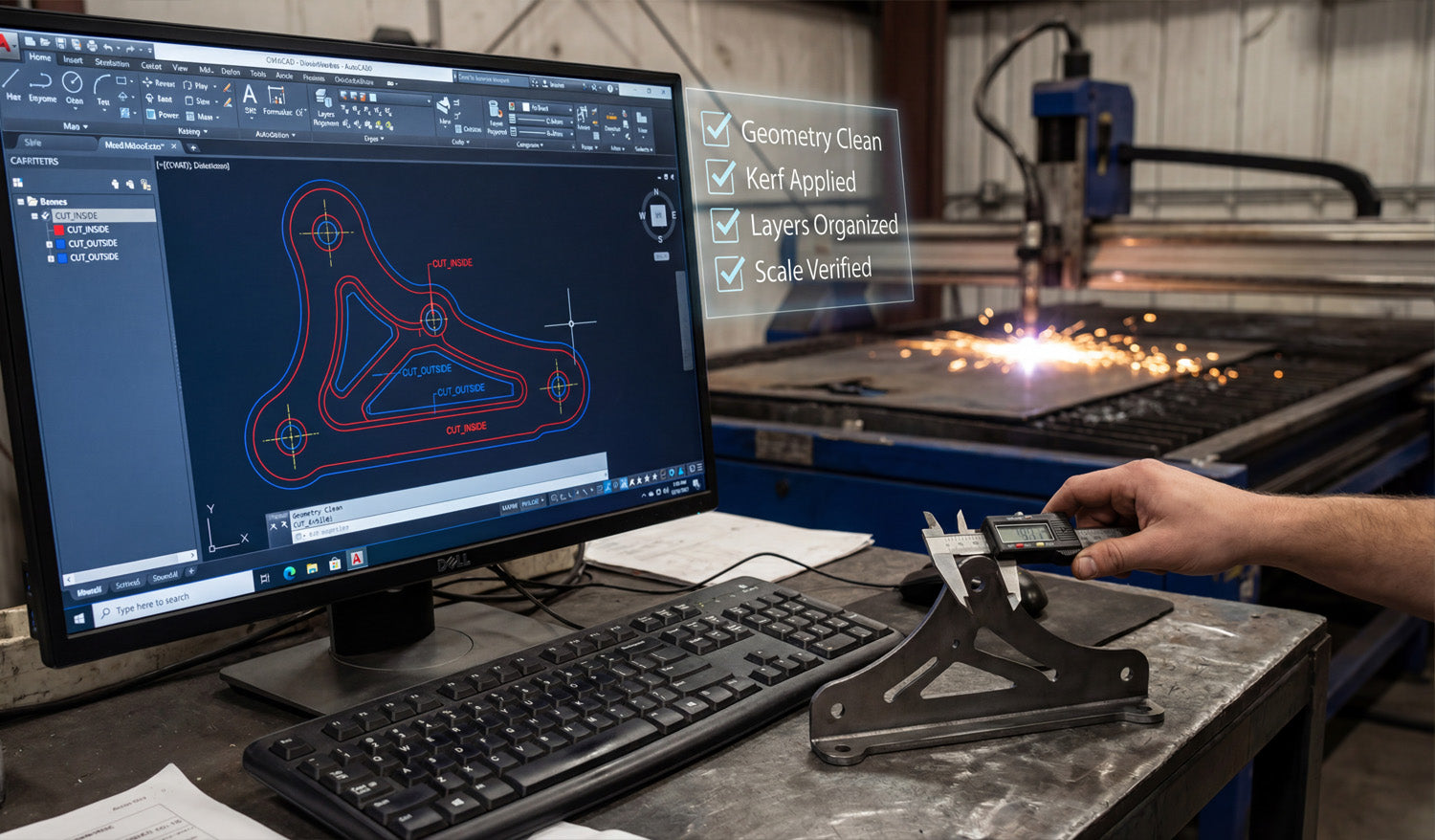
Every CNC cut is only as accurate as the design behind it. If your DXF file has sloppy dimensions, open paths, or random geometry, your laser, plasma, router, or water-jet will simply reproduce those errors in steel, wood, or acrylic. A precise DXF file, on the other hand, gives you:
- Cleaner edges with less grinding or sanding.
- Better fit between parts, tabs, slots, and bolt holes.
- Reduced scrap because you catch mistakes before cutting.
- Repeatable results for production runs and reorders.
The process below shows how to create precise CNC designs with DXF files from the very first sketch all the way to export.
Step 1: Define the Purpose and Requirements of Your Design
Before you open any software, be clear about what you are designing and how it will be used.
- What is the part? Metal art, a bracket, a sign, a furniture component, a panel?
- What material? Mild steel, stainless, aluminum, plywood, MDF, acrylic, or something else?
- What thickness? Material thickness affects minimum hole size, bridge width, and tab strength.
- What tolerances? Does it need to be decorative only, or does it have to fit tightly with other parts?
- Which machine? Laser, plasma, router, or water-jet, and what is the bed size?
These answers influence your minimum feature sizes, the amount of detail you can safely include, and the overall dimensions you should target.
Step 2: Set Up Your CAD Drawing Correctly
A precise DXF file starts with a clean drawing environment in your CAD or vector software.
- Choose units: Decide whether you will work in millimeters or inches and stick to it throughout the project.
- Set grid and snaps: Turn on grid, endpoint, and midpoint snaps to keep geometry aligned and clean.
- Create basic layers: For example, use layers like CUT_OUTSIDE, CUT_INSIDE, ENGRAVE, and REFERENCE.
- Set line weights and colors: Even if the machine ignores line weight, colors and layers help you keep the file organized.
Step 3: Draw the Base Geometry with Accuracy in Mind
Now you can start drawing the actual shapes of your CNC part or artwork.
- Use lines, arcs, and polylines instead of many tiny segments.
- Rely on dimensions and constraints where available, instead of “eyeballing” lengths and angles.
- Draw important reference geometry (like bolt circles, center lines, or bounding boxes) on a separate reference layer.
- For decorative designs, keep key shapes snapped to known points to avoid micro-gaps.
Take your time on this step. The more accurate your base drawing is, the less cleanup you will need later.
Step 4: Add Dimensions, Constraints, and Relationships
Precision is not just about drawing; it is about controlling how geometry behaves when you edit or rescale it.
- Apply dimensions to critical features such as hole diameters, slot widths, and overall height/width.
- Use constraints (horizontal, vertical, parallel, perpendicular, concentric) to keep geometry aligned.
- Lock key reference dimensions so accidental drags do not distort the design.
By constraining your sketch, you can adjust one or two main dimensions without breaking the entire design.
Step 5: Design for Kerf, Tool Diameter, and Material Limits
Real CNC machines remove material with a finite tool width (laser kerf, plasma kerf, or cutter diameter). Very fine details that look good on screen may disappear or break in real life.
- Kerf compensation: Plan for the cut width so inside and outside dimensions come out correctly.
- Minimum feature size: Make sure the smallest bridges and gaps are larger than your kerf and strong enough for the material.
- Corner radii: For routers, inside corners will always be rounded by the bit diameter. Design slots and pockets accordingly.
- Text and logos: Avoid ultra-thin fonts; choose styles and sizes that remain readable after cutting.
Step 6: Close All Paths and Clean Up the Geometry
Before you export to DXF, your geometry should be clean, closed, and free from errors.
- Close shapes: Ensure all cut profiles (outer borders and inner holes) are fully closed loops.
- Remove duplicates: Delete overlapping lines or stacked shapes that cause double cuts.
- Simplify curves: Use “simplify” or “optimize” tools to reduce unnecessary nodes while keeping shapes smooth.
- Delete stray objects: Remove tiny islands, construction lines, or leftover marks you do not want to cut.
Switch to an outline or wireframe view to see only curves and lines; this makes problems easier to spot.
Step 7: Organize Layers for CNC Operations
Organizing your layers pays off when you move into CAM or machine software.
- Assign outer profiles to one layer (for example, CUT_OUTSIDE).
- Assign inner holes and cutouts to another layer (for example, CUT_INSIDE).
- Put engraving, scoring, or marking on separate layers so they can be mapped to different power/speed settings.
- Keep non-cutting reference geometry on a layer you can easily turn off or exclude from export.
This structure makes it simple to tell your CAM software which paths to cut first, which to engrave, and which to ignore.
Step 8: Verify Scale and Add a Reference Dimension
Before you export the DXF, confirm that your design is correctly sized.
- Measure the overall width and height of the part and key internal features.
- Compare those measurements to your original design requirements or customer drawing.
- Optionally add a small reference rectangle or line (for example, exactly 100 mm wide) to help verify scale in CAM software.
If you later import this DXF into a different system, that reference value gives you a quick sanity check that units and scaling are correct.
Step 9: Export the Design as a Clean DXF File
Now you are ready to export.
- Use “Save As” or “Export” and choose DXF as the file type.
- Select a stable DXF version (often R12, R14, or a version your CAM software prefers).
- Turn off export of unnecessary items (like hatches or complex text) if they are not needed for cutting.
- Give the file a clear name that describes the part, material, and maybe size (for example, panel_bracket_6mm_steel.dxf).
Step 10: Test the DXF in Your CAM or Controller Software
Before you commit to production, test your exported DXF with the real CNC software.
- Import the DXF and check that layers map correctly to operations (cut, engrave, mark).
- Verify the measured size using the reference dimension or known features.
- Generate toolpaths and run a simulation to ensure the machine follows the intended routes.
- Cut a sample part on scrap material to verify fit, edge quality, and detail level.
If something is off, go back to the CAD file, correct the issue, and export a new DXF. Precise designs often go through one or two small iterations before they are production-ready.
Conclusion
Creating precise CNC designs with DXF files is a step-by-step process: define your requirements, set up your drawing environment, draw with accuracy, design for real-world kerf and material limits, clean up geometry, organize layers, and verify scale before you export. When you follow these steps, your DXF files become reliable digital blueprints that any compatible CNC machine can turn into accurate, repeatable parts—saving you time, material, and headaches on every project.


