CNC & DXF Design Guides
CNC & DXF Design Guides
The Best Tools for Working with DXF Files in CNC Projects
Using the right software tools for working with DXF files in CNC projects can save you hours of cleanup, reduce scrap, and help your laser, plasma, router, or mill run smoother and more profitably. Why Your DXF Toolchain Matters A DXF file is the bridge between your design ideas and your CNC machine. If you only use basic viewers or random editors, you end up fighting bad geometry, scale issues, and messy imports. A good DXF toolchain covers three main jobs: Creating and editing DXF designs (CAD and vector tools). Cleaning and optimizing DXF geometry for CNC. Converting DXF into CNC-ready toolpaths (CAM and controller software). Below are some of the best tool types to consider and how they fit into a clean, CNC-friendly workflow. 1. CAD Software for Drawing and Editing DXF Files CAD (Computer-Aided Design) software is often the primary tool for creating and editing DXF files. These tools give you precise control over dimensions, layers, and geometry. Professional CAD systems: Ideal when you need full control over dimensions, constraints, layers, and parametric design. Great for mechanical parts, brackets, fixtures, and sheet-metal patterns. 2D drafting tools: Lighter-weight alternatives focused on 2D drawings. Often enough for flat panels, signs, and decorative work. Key features to look for: Reliable DXF import/export with multiple version options. Support for layers, colors, and line types. Powerful snap and constraint tools for precise geometry. Options to simplify curves and manage node counts. If your CAD system can produce clean DXF files with correct units and layers, every other step in your CNC workflow becomes easier. 2. Vector Graphics Editors for Artwork and Logos For signs, wall art, logos, and decorative panels, vector graphics software can be just as important as CAD. These tools are great for freeform artwork that still needs to export as DXF. Ideal use cases: Logos, text-based designs, monograms, ornaments, and intricate line art. Useful features: Converting text to outlines so it engraves or cuts correctly. Path operations like union, subtract, and intersect for building complex shapes. Control over strokes vs fills to match your laser or router workflow. Export options for DXF and SVG, often used together in CNC jobs. When paired with a CAD tool, a vector editor lets you blend clean engineering geometry with creative artwork inside the same DXF pipeline. 3. DXF Viewers and Quick Inspection Tools Before a file ever reaches CAM or a CNC machine, a simple DXF viewer can help you catch obvious problems quickly. What these tools are best for: Checking overall size and verifying units. Inspecting layer structure and colors. Looking for broken profiles or missing details. Benefits: They are fast, lightweight, and easy for operators to use without touching the master design file. Using a dedicated viewer as a “first pass” saves time and keeps accidental edits out of your main CAD projects. 4. DXF Cleanup and Optimization Utilities Even well-designed DXF files can pick up errors: duplicate lines, tiny gaps, or too many nodes from tracing or heavy editing. Cleanup tools are designed to fix these issues. Key cleanup functions: Remove duplicates: Deletes overlapping lines that cause double cuts. Close gaps: Joins near-miss endpoints into fully closed contours. Simplify paths: Reduces node count on curves while preserving shape. Remove junk geometry: Gets rid of tiny islands, stray points, and unused blocks. Why this matters: Cleaner DXF geometry means faster toolpaths, fewer crashes, and better surface quality on your CNC machine. You can often do basic cleanup inside CAD or vector editors, but specialized tools or scripts can save time when you process lots of files. 5. CAM Software for Turning DXF into Toolpaths CAM (Computer-Aided Manufacturing) software is where your DXF becomes real machine motion. This is a critical part of any CNC toolkit. For lasers and plasmas: Import DXF and assign cut, engrave, and score operations. Set power, speed, frequency, and cut order. Apply kerf compensation and generate optimized toolpaths. For routers and mills: Turn DXF contours into profiles, pockets, and drilling cycles. Manage tools, stepdowns, stepovers, and finishing passes. Handle multiple setups and work coordinate systems when needed. What to look for: Good DXF handling, solid simulation, and a post-processor that matches your specific controller. Strong CAM software is what turns your DXF library into production-ready CNC code. 6. Nesting Software for Sheet-Based CNC Cutting If you cut a lot of parts from sheet material (metal, plywood, acrylic), nesting tools are a must-have. They work hand-in-hand with DXF files. Core functions: Import multiple DXF parts and arrange them on a sheet. Automatically rotate and pack parts to maximize material use. Separate jobs by material, thickness, and machine. Benefits: Less scrap, fewer sheets used, and cleaner job organization. Some CAM systems include basic nesting; dedicated nesting tools often give better control and tighter layouts, especially for production shops. 7. Text and Font Tools for DXF-Based CNC Projects Text is a surprisingly tricky part of many CNC jobs—especially for cut-out signs and stencils. Specialized text tools help you convert fonts into safe, CNC-ready vectors. Important capabilities: Convert text to outlines while maintaining good curve quality. Create stencil fonts where inner islands of letters are bridged. Adjust spacing and stroke thickness for readability after cutting. Why it matters: Good text tools prevent letters from falling apart and make signs, nameplates, and monograms look professional. 8. Measurement and Inspection Tools Inside DXF Editors A lot of DXF work is about verifying that designs match your real-world needs. Built-in measurement and inspection tools in CAD/vector editors are essential. Use distance and angle tools to verify critical dimensions. Check hole spacing and slot widths for fit with mating parts. Measure bridge widths and minimum feature sizes against your kerf and material limits. These simple tools help you catch design issues before they show up as scrap on the CNC table. 9. Scripting and Automation Tools for Bulk DXF Work If you handle large numbers of DXF files, scripts and automation tools can be game-changers. What you can automate: Batch renaming and organizing DXF libraries. Automatic cleanup steps (remove duplicates, delete certain layers). Exporting multiple formats from a master design set (DXF, SVG, PDF). Where they run: Inside CAD software as macros, in separate automation tools, or via command-line scripts. For serious CNC businesses with big design catalogs, a small investment in automation can save huge amounts of repetitive work. 10. File Management Tools for DXF Libraries As your DXF collection grows, simple file storage is not enough. You need a system. Folder structure: Organize by process (Laser, Plasma, Router), then by category (Animals, Signs, Panels, Brackets). Naming standards: Include size, material, and version in filenames where it matters. Backups and sync: Use backup tools or cloud sync so your DXF library is safe and accessible from multiple machines. Good file management tools keep your DXF designs from getting lost and help operators quickly find the right file for each job. How to Build Your Ideal DXF Tool Stack You do not need every tool on this list on day one. Start from your main CNC process and build from there: Pick a CAD or vector editor you like for design and basic editing. Add a CAM package that works well with your machine and imports DXF cleanly. Introduce cleanup and nesting tools as your job volume grows. Layer in automation and library management when you are handling many designs or running production. Over time, refining your DXF tool stack is one of the most effective ways to improve CNC productivity without changing your hardware at all. Conclusion The best tools for working with DXF files in CNC projects are the ones that cover your full workflow—from accurate drawing and clean geometry to smart nesting and reliable toolpaths. By combining strong CAD and vector tools, dedicated cleanup utilities, capable CAM software, and solid file management, you can turn raw DXF designs into CNC-ready jobs with less friction and more control. Build your stack step by step, and your DXF files will become a true competitive advantage for every laser, plasma, router, and milling project you run.
How to Convert DXF Files into CNC-Ready Files for Different Machines
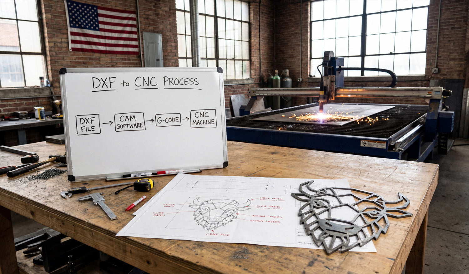
Converting DXF files into CNC-ready files is all about taking clean 2D geometry and turning it into the right toolpaths and machine code for your laser, plasma, router, or milling machine. DXF vs CNC-Ready Files: What’s the Difference? A DXF (Drawing Exchange Format) file is a 2D vector drawing: lines, arcs, and curves. It describes the shape of your part or artwork, but it does not tell a CNC machine how fast to move, how deep to cut, or what order to follow. CNC-ready files, on the other hand, are machine instructions. They are usually: G-code files (for routers, mills, some lasers and plasmas) with extensions like .nc, .tap, or .gcode. Controller-specific job files for branded laser and plasma systems. The goal is simple: start with a clean DXF, process it in CAM or controller software, and export the correct CNC-ready file for your specific machine. Step 1: Clean and Prepare Your DXF File Before you convert anything, make sure your DXF file is in good shape. A clean DXF makes every later step easier. Check units and scale: Confirm whether the design is in millimeters or inches and verify a key dimension. Close all profiles: Outer shapes and inner cutouts should be closed loops with no small gaps. Remove duplicate lines: Delete overlapping or stacked paths so the machine does not cut the same line twice. Simplify curves: Reduce unnecessary nodes on curves for smoother motion. Use layers: Separate cut, engrave, score, pockets, and reference geometry onto different layers if possible. Step 2: Choose the Right CAM or Controller Software DXF files are neutral. To turn them into CNC-ready files, you need CAM (Computer-Aided Manufacturing) or machine control software that understands both DXF and your machine. Laser cutters: Often use built-in controller software that imports DXF and lets you set power and speed per layer/color. Plasma tables: Use CAM software to create lead-ins, pierces, and kerf-compensated toolpaths from DXF geometry. CNC routers: Use CAD/CAM packages that can turn DXF profiles into 2D/2.5D toolpaths (profile, pocket, drill). CNC mills: Use CAM systems that support contouring, pockets, drilling cycles, and multiple coordinate systems. Pick the software that matches your machine brand, control type, and the complexity of your projects. Step 3: Import the DXF and Confirm Geometry Once you open the DXF in CAM or controller software, verify that everything came in correctly. Check the overall size and compare it to your design plan. Confirm that layers and colors are still present and readable. Look for broken contours, tiny gaps, or missing shapes that might not have imported correctly. Delete any dimensions or reference geometry that you do not want the CNC to follow. Step 4: Assign Operations to Geometry Now tell the software what each line or shape in the DXF is supposed to do. Profile cuts: Outside outlines and internal cutouts that should go all the way through. Pockets: Areas where you want to remove material to a certain depth (router and mill). Engraving / scoring: Light surface lines for logos, text, and guides. Drilling: Holes that are better done with drill cycles than with profile cuts. Many CAM packages let you select by layer or color, which makes this step much faster when your DXF is well organized. Step 5: Apply Machine-Specific Settings This is where you convert neutral DXF geometry into real-world machining instructions. Each machine type needs different settings. For CNC Laser Cutting Set power, speed, and frequency for each layer (cut, engrave, score). Choose cut order (inner shapes first, outer profiles last). Decide between vector-only (lines and curves) and raster engraving for fills. Apply kerf compensation if supported, or adjust dimensions in the DXF for critical fits. For CNC Plasma Cutting Set material type and thickness in the CAM software. Define kerf width, lead-ins, and lead-outs for each contour. Configure pierce height, cut height, and pierce delay for clean starts. Optimize cut order to reduce warping and minimize pierces. For CNC Routers Choose the right tool diameter, flute count, and material in the tool library. Set spindle speed, feed rate, and plunge rate based on material and tool. Define cut strategies: profile inside / outside, pocketing, and drilling. Add tabs to hold parts in place during cutting. Apply stepdown (depth per pass) and stepover for efficient removal. For CNC Milling Machines Set up your work coordinate system (WCS) and origin (corner, center, or feature). Assign roughing and finishing toolpaths to contours and pockets. Use correct drilling cycles (peck, tap, ream) for hole geometry. Define depths, stepdowns, feeds, and speeds with respect to tool and material. Step 6: Generate Toolpaths and Simulate Once operations and settings are in place, tell the CAM software to create toolpaths. Check that all outer edges are cut from the correct side (inside vs outside compensation). Verify that all holes and pockets are included and at the correct depth. Run a simulation to see how the tool moves and how long the job will take. Look for collisions, air cuts, or strange moves that suggest a setup problem. Simulation is your chance to catch mistakes before they damage material or tools. Step 7: Post-Process to Create CNC-Ready Files Post-processing is the final step that converts toolpaths into the exact format your machine controller expects. Choose the correct post-processor for your machine (for example, GRBL, Mach3, Fanuc, or a brand-specific post). Export the program with a clear name, such as partname_machine_material_v1.nc. Review the generated code if you are comfortable reading G-code (optional but helpful). Now you have a CNC-ready file that your machine can run, generated from your original DXF design. Step 8: Run Test Cuts and Refine For new designs or new materials, always test before full production. Run the program on scrap or offcut material first. Check fit, edge quality, and detail (especially holes, tabs, and thin features). Adjust feeds, speeds, power, or kerf compensation as needed. Update your CAM setup and re-post the CNC-ready file once you are satisfied. Save your successful DXF + CAM + post-processor combination as a template for future jobs. Quick Reference: DXF to CNC-Ready by Machine Type Machine Type From DXF You Need To CNC-Ready Output Laser Cutter Assign cut / engrave / score layers, set power & speed, choose cut order. Laser job file or G-code depending on controller. Plasma Cutter Set material, kerf, lead-ins/outs, pierce settings, and cut direction. G-code or table-specific job file. CNC Router Pick tools, feeds, speeds, pockets, profiles, tabs, and depths per pass. G-code (e.g., .nc, .tap, .gcode). CNC Mill Define WCS, contours, pockets, drilling cycles, rough/finish paths. Controller-specific G-code program. Conclusion Converting DXF files into CNC-ready files is a repeatable process: clean the geometry, import into CAM or controller software, assign operations, apply machine-specific settings, generate toolpaths, and post-process to the correct code format. When you follow these steps—and tune them for each type of machine—you can take any good DXF design and turn it into reliable, production-ready CNC programs for lasers, plasmas, routers, and mills with confidence.
Top Tips for CNC Design Success: Mastering DXF Files
Mastering DXF files is the fastest way to improve your CNC design success, cut cleaner parts, and move from idea to finished product with less stress, less scrap, and more profit. Why DXF Files Are So Important for CNC Design DXF (Drawing Exchange Format) is the universal language of 2D CNC work. Whether you run a laser, plasma, router, or milling machine, DXF files act as the bridge between your design software and your CNC controller. When your DXF files are clean, organized, and designed with the machine in mind, you get: Smoother toolpaths and better edge quality. Shorter setup and programming time. More predictable results from job to job. Fewer surprises on the machine and less rework. Tip 1: Start with a Clear Design Intent Before you draw a single line, define what you are trying to achieve with the part or artwork. Function: Is it decorative wall art, a structural bracket, a sign, a fixture, or a part for assembly? Machine type: Laser, plasma, router, or mill—each has different strengths and limits. Material: Steel, stainless, aluminum, MDF, plywood, acrylic, or something else? Finish: Will the part be painted, powder-coated, polished, or left raw? A clear design intent helps you make smarter choices about feature sizes, text thickness, joint types, and overall detail level in your DXF file. Tip 2: Work in the Right Units from the Start Unit issues are one of the most common hidden problems in CNC design. Get this right at the beginning. Choose millimeters or inches as your standard and stick to it in both CAD and CAM. Set your design template to the correct units so every new DXF starts correctly. Include at least one known dimension (for example, a 100 mm or 4 inch reference) to verify scale after import. Good DXF files open at the correct size with no guessing, making life easier for whoever runs the machine. Tip 3: Keep Geometry Clean, Closed, and Connected Clean geometry is the foundation of CNC success. Dirty DXF files cause broken cuts, strange toolpaths, and wasted time. Close all profiles: Outer shapes and inner cutouts should be fully closed loops with no gaps. Remove duplicate lines: Delete overlapping paths so the machine does not cut the same line twice. Eliminate stray elements: Get rid of tiny segments, points, and construction marks that are not part of the final cut. Use polylines: Combine separate segments into continuous polylines where possible for smoother motion. Spending a few minutes cleaning your DXF before CAM can save you hours of troubleshooting on the CNC table. Tip 4: Control Node Count for Smooth CNC Motion Too many nodes (control points) make your machine stop and start constantly, leading to rough edges and slower cuts. Use simplify or optimize curve commands to reduce node density on curves. Convert “stair-stepped” curves or auto-traced outlines into smooth arcs or splines. Target areas with heavy detail: tight corners, curves from traced images, and decorative textures. Your goal is to keep the visual shape the same but let the CNC machine follow it with fewer, smoother moves. Tip 5: Design with Your CNC Machine in Mind Each type of CNC machine has its own design rules. Mastering DXF means respecting those limits from the start. Laser: Can handle fine detail, but very thin bridges in thin material may burn away. Plasma: Has a wider kerf; avoid tiny holes and micro text, and use thicker bridges. Router: Uses round bits; inside corners must have a radius or dogbone/T-bone relief. Milling: Needs tool access; deep pockets and narrow slots must match your tool length and diameter. A DXF that is “machine-aware” is much easier to run at speed without breaking tools or losing detail. Tip 6: Use Layers to Separate Operations Layers turn a messy drawing into a structured CNC plan. They help CNC operators see exactly what each line is meant to do. Create layers like CUT_OUTSIDE, CUT_INSIDE, ENGRAVE, SCORE, and HOLES. Place through-cuts on one layer and engraving or marking on another. Use a reference layer for centerlines, dimensions, and datums that should never be cut. Assign distinct colors to layers if your CAM or controller uses color mapping. When the DXF reaches CAM, you can map entire layers to speed, power, and depth settings with just a few clicks. Tip 7: Respect Kerf, Minimum Feature Size, and Material Strength Designing without thinking about kerf and material behavior is a fast way to create beautiful but unusable parts. Know your kerf width (cut width) for each process and material. Make sure bridges, webs, and thin features are wider than the kerf and strong enough for handling. Leave enough material around holes and slots so parts do not warp or break. For joints, design slots and tabs with realistic tolerances so they fit after kerf compensation. Good DXF design is about balancing visual detail with what the material and machine can reliably produce. Tip 8: Make Text and Logos CNC-Friendly Text and logos often cause problems in CNC design because they start as fonts or bitmaps rather than clean vectors. Convert text to curves/outlines before exporting to DXF so it does not depend on missing fonts. Use stencil-style lettering for cut-out text so inner islands (A, O, P, R, D, etc.) do not fall out. Keep stroke widths thick enough for your material and machine process. For logos, clean up traced artwork by removing unnecessary nodes and small, fragile shapes. Well-prepared text and logos give you clear engravings and cut-outs that hold their shape and stay readable. Tip 9: Build and Organize a Reusable DXF Library One of the biggest “pro moves” in CNC design is building your own DXF library instead of starting from zero every time. Save proven parts—tabs, brackets, gussets, hinges, logos—as separate DXF files or blocks. Organize them by category: Structural, Decorative, Fixtures, Logos, Panels, and so on. Use clear naming: include size, material, and version where it makes sense (for example, hinge_80mm_steel_v2.dxf). Keep notes or a text file with best-known settings and common uses for each design. Over time, this library becomes a powerful asset you can reuse across projects, saving huge amounts of design and CAM time. Tip 10: Test on Scrap and Refine Your DXF Designs No matter how good your DXF looks on screen, the real proof is on the machine. Cut small samples on scrap material before committing to full sheets or production runs. Check fit, edge quality, and strength of joints, bridges, and small features. Adjust the DXF where needed: widen slots, thicken weak areas, simplify details that do not cut well. Save improved versions of your DXFs with new version numbers so you always know which one works best. Think of each test as an investment in a stronger, more reliable design that will serve you many times in the future. Tip 11: Avoid the Most Common DXF Mistakes To master DXF files for CNC, stay away from these classic pitfalls: Designing “for the screen” only: It looks great in CAD, but ignores kerf, material thickness, and machine limits. Leaving messy geometry: Open paths, duplicates, and stray lines that cause unexpected cuts. Ignoring layers: Putting everything on “Layer 0” and making CAM setup slow and confusing. Using raw auto-traced images: Outlines full of noise and micro segments that kill cutting speed. No unit or scale check: Importing a part and discovering it is 10× too small or too large after programming. Tip 12: Standardize Your DXF Workflow Finally, turn your best practices into a repeatable process so every new design starts strong. Create a DXF template file with layers, colors, and units preconfigured. Use a short checklist before export: closed paths, no duplicates, correct scale, simple curves, proper layers. Document your internal standards for bridge width, minimum feature size, and text height per material. Train everyone on your team to follow the same steps so files are consistent regardless of who designed them. This kind of standardization is what separates hobby-level work from a professional CNC design and manufacturing workflow. Conclusion Top CNC design success is not about having the most powerful machine—it is about feeding that machine well-built DXF files. By starting with clear design intent, keeping geometry clean, respecting your machine and material limits, using layers wisely, and building a reusable DXF library, you turn each drawing into a reliable CNC blueprint. Mastering DXF files is how you move from guesswork and rework to predictable, profitable CNC projects on every job.
How to Create Multi-Layered DXF Files for CNC Laser Projects
Creating multi-layered DXF files for CNC laser projects lets you control cutting, engraving, and marking in a clean, organized way so every pass of the laser is faster, safer, and easier to set up. What Is a Multi-Layered DXF File? A multi-layered DXF file is a drawing where different parts of your design are separated onto layers (and often colors). Each layer usually represents a different operation on the laser: One layer for through-cuts (outer shapes, holes). One layer for engraving (logos, text, fills). One layer for scoring or light lines (fold lines, guides). Optional layers for reference geometry (construction lines, dimensions). When you import this DXF into your laser software, you can assign different speeds, powers, and passes to each layer instead of selecting items one by one. Step 1: Plan Your Laser Operations First Before you open your CAD or vector software, think about what the laser actually needs to do. Will you only cut, or do you also need engraving and scoring? Which lines should be deep and dark, and which should be light guides? Do you have areas that must be filled (raster-like engraving) versus simple outlines? Turn that plan into a short list of operations. For example: Layer 1 – Cut (through-cut). Layer 2 – Engrave (medium power, slower speed). Layer 3 – Score (low power, high speed). Layer 4 – Reference (not sent to the laser). Step 2: Set Up Layers in Your CAD or Vector Software Next, create layers in your drawing program that match your operation plan. Create a new file with the correct units (mm or inches). Add layers with clear names like L-CUT, L-ENGRAVE, L-SCORE, and L-REF. Assign distinct colors to each layer (your laser software can use these colors as mapping targets). A simple, consistent naming style makes it much easier to reuse and scale your workflow across many projects. Step 3: Draw and Assign Geometry to the Correct Layers Now you can build your design and place each element on the right layer. Put all outer profiles and holes that should be fully cut through on the L-CUT layer. Place logos, decorative outlines, and text you want engraved (not cut through) on the L-ENGRAVE layer. Use the L-SCORE layer for fold lines, assembly guides, or light markings. Keep construction geometry—centerlines, alignment marks, dimensions—on L-REF so you can hide or delete it before export. If you move or copy elements, double-check that they stay on the correct layer; many programs quickly show the active layer in the interface. Step 4: Use Colors to Match Your Laser’s Settings Most CNC laser controllers let you map colors to different power and speed values. You can use this to make your DXF “machine-ready.” Assign a unique color to each major layer (for example, red for cut, blue for engrave, green for score). Use solid lines only (no fills or hatches) for vector operations. Keep the same color scheme across all projects so you can reuse settings in your laser software. Later, when you import the DXF, you simply tell the laser: “Red lines = cut, 80% power; Blue lines = engrave, 20% power,” and so on. Step 5: Manage Line Types and Stroke Weights Line thickness in the DXF does not change the physical kerf of the laser, but it can help you visually organize and avoid mistakes. Use a standard thin stroke for all cutting and engraving paths. Optionally use dashed or dotted lines on reference layers for construction or fold guides. Avoid heavy line weights that may export poorly or confuse your laser software. Keep in mind that most laser controllers only care about the vector path itself, not the stroke width—so the visual styling is just for your editing comfort. Step 6: Add Registration and Alignment Marks on Separate Layers For multi-step or multi-material projects, you may need registration marks to align different passes or colors. Create an L-REG layer just for alignment marks (small crosses or circles). Place the marks in consistent positions relative to your artwork (corners, midpoints, or known offsets). Decide whether these marks should be lightly engraved, cut, or only used for positioning and then removed. If you engrave and cut in separate jobs or on different materials, matching registration marks makes it much easier to keep everything lined up. Step 7: Organize Filled Areas vs Outlines Many CNC laser projects need both vector lines and filled engraving areas (for example, solid logos, badges, or backgrounds). Keep outlines and borders on their usual cut/engrave layers. For filled areas, create separate fill regions on an engraving layer or assign them a specific color. Some workflows convert these fills to hatch patterns or treat them as raster engravings at the CAM stage. Clearly separating outlines from fill regions in your DXF makes it easier to adjust engraving depth and texture without changing the main shapes. Step 8: Check Geometry Quality on Each Layer Before exporting, zoom in and make sure each layer is clean and laser-ready. Verify that all cut paths are closed loops with no gaps. Check that engraving and scoring lines do not have duplicate or overlapping segments. Reduce unnecessary nodes on curves so the laser head can move smoothly. Delete or hide reference layers that should not be sent to the laser (unless your software can ignore them by layer or color). A quick per-layer review saves you from surprises at the machine and reduces setup time in the laser software. Step 9: Export a Clean Multi-Layer DXF When your design is ready, it is time to export a DXF file that preserves your layer structure. Use Save As or Export and choose a DXF version compatible with your laser software (often R12/R14 works well). Make sure the option to include layers and colors is enabled. Give the file a clear name that hints at material and size, such as multi_layer_sign_acrylic_300mm.dxf. After export, open the DXF in a viewer or your laser CAM software to confirm that layers and colors carried through correctly. Step 10: Map Layers to Laser Settings in Your Controller In your laser control software, import the DXF and connect each layer or color to the correct cutting parameters. Assign cut layers to high power, medium speed, and through-cut mode. Assign engrave layers to lower power, slower speed, and appropriate line or fill mode. Assign score layers to very low power, fast speed for light surface marks. Decide whether registration or reference layers should be ignored, scored, or engraved lightly. Once you dial in good settings, save them as presets so the next multi-layer DXF with the same color scheme can be set up in seconds. Common Mistakes When Creating Multi-Layer DXF Files Watch out for these issues that can cause confusion or wasted material: Mixing operations on one layer: Putting cut and engrave lines together on the same layer makes setup slower and riskier. Inconsistent color usage: Changing which color means “cut” from project to project leads to mistakes. Forgotten reference geometry: Leaving dimensions or construction lines active in the DXF can create unwanted marks. Overlapping cut and engrave paths: Duplicate geometry on different layers can cause double passes in the same location. Practical Tips for Building a Reusable Multi-Layer Workflow Use the same layer names and colors across all projects. Create a template file with layers, colors, and line types preconfigured. Write a short legend in the notes: which layer = which operation and typical power/speed. Save “test coupons” in your library that use all your standard layers so you can quickly re-tune settings on new materials. Over time, this consistency turns multi-layer DXF setups into a fast and reliable part of your CNC laser workflow. Conclusion Creating multi-layered DXF files for CNC laser projects is one of the best ways to keep your designs organized and your jobs easy to run. By planning your operations, setting up clear layers and colors, assigning the right geometry to each layer, and exporting a clean DXF, you give your laser software everything it needs to apply precise power, speed, and order to every line. The result is less setup time, fewer mistakes, and laser projects that move smoothly from design to finished part.
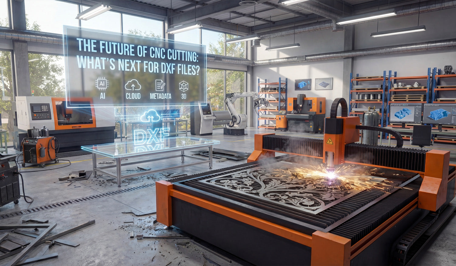
The Future of CNC Cutting: What’s Next for DXF Files?
The future of CNC cutting will still include DXF files at the core, but they will be smarter, cleaner, and more connected to cloud, AI, and automation workflows. DXF Is Not Going Away Any Time Soon Despite new formats and 3D workflows, DXF remains one of the most trusted ways to move 2D geometry between CAD, CAM, and CNC machines. Almost every laser, plasma, router, and water-jet system can read DXF directly or through a simple import step. Because so many shops, design libraries, and CAM tools rely on DXF, it is far more likely to evolve than to disappear. The future of CNC cutting will probably look like “DXF plus extra intelligence,” not “no DXF at all.” Trend 1: Smarter, AI-Assisted DXF Cleanup Today, a lot of time is spent cleaning DXF files by hand: closing gaps, removing duplicates, reducing nodes, and fixing small geometry errors. In the future, more of this work will be automated. Automatic repair: Tools will detect open paths, overlapping lines, and bad splines and fix them in one click. AI-based simplification: Systems will recognize “visual detail” vs “noise” and remove extra nodes without changing how the design looks. Process-aware editing: Software will optimize DXF files differently for laser, plasma, router, or milling based on your chosen machine. This means you will spend less time cleaning files and more time actually cutting parts or building products. Trend 2: DXF Files with Richer Metadata Classic DXF files mainly store geometry. The future will likely add more context directly around that geometry. Material hints: Recommended materials and thickness ranges stored as metadata. Preferred settings: Suggested speeds, powers, or feeds and speeds linked to the design. Manufacturing notes: Information about minimum bridge sizes, best nesting orientation, or optional engraving layers. Instead of a “dumb” drawing, DXF files will act more like mini CNC recipes that help you get to a good cut faster—even if you are importing the design into a new CAM system. Trend 3: Cloud-Based DXF Libraries and Collaboration More CNC shops are moving their design libraries to the cloud. That changes how DXF files are stored, shared, and updated. Central libraries: Teams will access the same DXF collections from any machine or location. Version tracking: Changes to a DXF file—slot sizes, hole patterns, logo updates—will be tracked like code changes in software projects. Instant distribution: When a design is improved or fixed, every operator gets the updated DXF immediately. For digital design shops, this also means customers can browse online collections, purchase commercial bundles, and download cut-ready DXF files directly into their own CNC workflow. Trend 4: Tighter Integration with 3D Workflows Even though DXF is a 2D format, it will remain an important bridge between 3D models and real CNC cutting. Automated profile extraction: CAM tools will pull 2D views and section profiles from 3D models and export them as DXF for flat cutting. Sheet-metal workflows: Unfolded flat patterns (developed blanks) will be saved as DXF for cutting before bending and forming. Fixture plates and templates: Complex 3D fixtures will use DXF-based plates and drilling patterns as part of the overall setup. In many shops, the future will look like: model in 3D, generate critical 2D profiles as DXF, then cut them on laser, plasma, or router tables as part of a bigger, mixed process. Trend 5: DXF Files Tuned for Automation and Lights-Out Production As more CNC shops push toward automation and lights-out cutting, DXF files will need to be more predictable and standardized. Standardized layers: Layer naming and color conventions will be aligned with automated CAM templates. Ready-to-nest shapes: DXF profiles will be designed for dense nesting and minimal scrap right from the start. Error-free geometry: Automated pipelines will reject DXF files that do not meet certain quality rules (closed loops, no duplicates, valid scale). Clean, standardized DXF designs will flow from online libraries into nesting software, into the machine queue, and onto the table with very little human intervention. Trend 6: Hybrid Vector–Raster Workflows for Engraving Laser engraving is already moving toward hybrid workflows where vector and raster data work together. DXF will stay important on the vector side. Mixed jobs: DXF outlines for cutting and scoring, combined with bitmap layers for photo engraving. Procedural fills: Vector borders and regions defined in DXF, filled with hatch patterns or shading controlled at the CAM stage. Parametric personalization: Names, numbers, and logos updated automatically inside a DXF-based template for batch engraving jobs. In this future, DXF files define the “structure” of the design, while engraving styles and textures are applied dynamically at the machine level. Trend 7: More DXF Content, Fewer “Random” Designs The CNC world already has thousands of DXF files online, but many are low quality or not truly cut-ready. The next wave will focus on curated, well-tested content. Production-grade bundles: Large DXF libraries optimized for real machines and real materials. Proven designs: Files that have been cut, refined, and documented with recommended settings. Category depth: Specialized sets for wildlife art, architectural panels, brackets, fire pits, yard art, and more. For CNC businesses, the value will shift from “any DXF” to “the right DXF”—files that cut cleanly, nest well, and turn into products that customers actually want to buy. Trend 8: DXF as Part of a Full Digital Product Ecosystem Finally, DXF files will increasingly be seen as part of a bigger digital product, not just a raw drawing. Multi-format packs: DXF bundled with SVG, AI, PDF, and high-resolution preview images. Documentation: Cut examples, photos of finished products, and notes on how to sell or display them. Licensing and tracking: Clear license terms and purchase records for shops that sell physical products made from the designs. This ecosystem perspective turns a single DXF file into a complete, reusable asset for makers, fabricators, and CNC businesses. What This Means for CNC Shops and Makers For most CNC users, the message is simple: DXF is here to stay, but it is becoming more powerful. Invest in clean, high-quality DXF libraries instead of random, untested files. Adopt consistent DXF standards for layers, naming, and quality checks in your own shop. Be ready to plug into cloud, AI, and automated CAM tools that will make your DXF workflow even faster. If you build good habits now—file organization, clean geometry, and reliable design sources—you will be ready for whatever the future of CNC cutting brings to DXF files and beyond.
Advanced Techniques for Editing DXF Files for CNC Applications
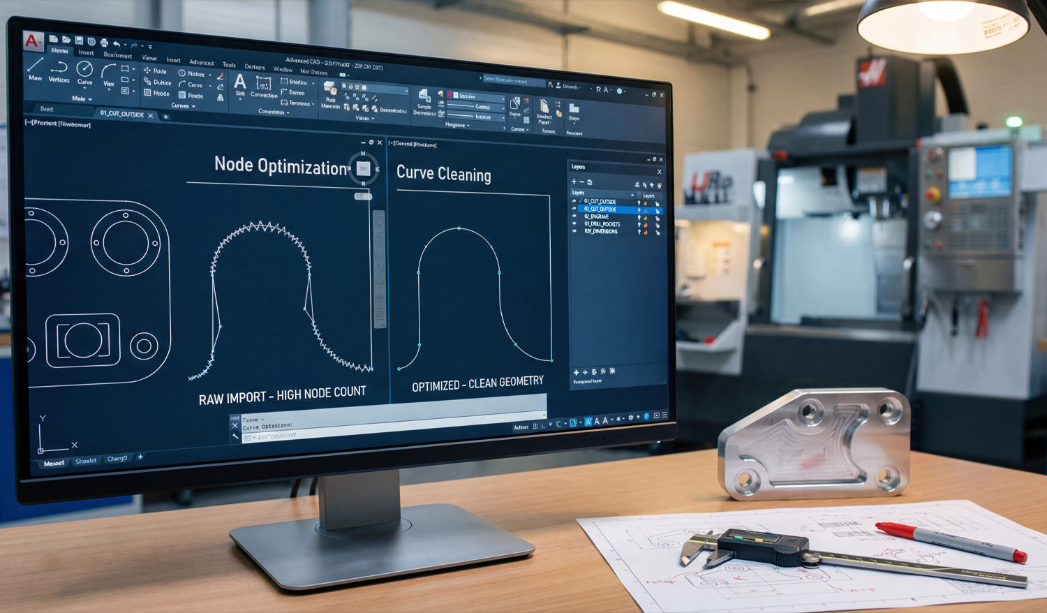
Advanced techniques for editing DXF files let you clean geometry, control detail, and tailor designs for specific CNC machines so you get faster setup, smoother toolpaths, and more reliable results. Why Advanced DXF Editing Matters for CNC Applications Basic DXF editing is enough for simple parts, but real CNC work—especially in production—demands more control. When you know how to refine and optimize DXF files at a deeper level, you can: Reduce CAM setup time and manual cleanup on every job. Improve edge quality by smoothing motion and cutting down on micro-moves. Create machine-specific versions that fit laser, plasma, router, or mill workflows. Standardize parts so they are easier to reuse, nest, and scale across projects. Think of advanced DXF editing as “pre-engineering” your files so every downstream step—CAM, nesting, and cutting—runs smoother. 1. Work Non-Destructively: Master vs Production DXF Files A key advanced habit is separating your “design master” from your “production-ready” DXF files. Master file: The clean, fully editable design (often CAD, AI, or SVG) where you keep rich detail and construction geometry. Production DXF: A simplified, optimized version tuned for a specific CNC process. Workflow tip: Always save a copy before making heavy optimizations, scaling, or deleting construction lines. Keep master and production files in separate folders so shop-floor edits never overwrite your originals. Use clear naming, such as panel_master.dwg and panel_laser_3mm_production.dxf. This non-destructive approach lets you experiment with aggressive optimizations while keeping a “clean source of truth.” 2. Advanced Layer Strategies and Naming Conventions Layers are not just for organization—they are powerful tools for advanced control of CNC operations. Operation-based layers: Separate CUT_OUTSIDE, CUT_INSIDE, ENGRAVE, MARK, and DRILL. Depth-based layers: For routing or milling, name layers by depth (for example, POCKET_Z-3, POCKET_Z-6). Machine-specific layers: Use LASER_ONLY, PLASMA_ONLY, or ROUTER_ONLY to enable or disable features per machine. Reference layers: Put datums, dimension lines, and setup aids on REF layers that never get cut. When you import a layered DXF into CAM, you can assign feeds, speeds, and cutting order to an entire layer in seconds instead of selecting geometry by hand. 3. Node Optimization and Curve Cleaning Many DXF files, especially those traced from images, are overloaded with nodes. This causes jerky tool motion and slow cutting. Advanced editing focuses on cleaning curves while preserving shape. Simplify curves: Use “simplify” or “fit curve” tools to reduce node count on arcs and splines. Replace polylines with arcs: Where possible, convert jagged polyline arcs into real circular arcs. Control tolerance: Adjust simplification tolerance so the curve stays visually accurate but lean. Target high-density zones: Zoom into corners and tight curves where extra nodes cause the worst slowdowns. Goal: fewer nodes, smoother motion, and less “stop–go” behavior from your CNC machine without changing the design’s look. 4. Using Boolean Operations for Smart Geometry Editing Boolean tools—union, subtract, and intersect—are essential for building and editing complex CNC-ready shapes. Union (combine): Merge overlapping shapes into a single contour for cleaner outer profiles. Subtract: Use shapes to carve holes, windows, and negative spaces out of a base plate. Intersect: Extract shared regions from overlapping designs to create new hybrid artwork. Advanced trick: design “tool blocks” (for example, standard slots, dogbone corners, decorative cutouts) and subtract or union them with main parts to build consistent, reusable geometry across products. 5. Parametric Editing with Constraints and Reusable Blocks Even though DXF itself is a 2D exchange format, you can use parametric CAD features before export to make editing faster and more precise. Constraints: Apply horizontal, vertical, parallel, and concentric constraints so geometry stays aligned when dimensions change. Dimensions: Drive important features (slot widths, hole patterns, panel sizes) with numeric parameters. Blocks or symbols: Turn common features (bolt circles, hinge cutouts, tabs) into reusable blocks that update everywhere when edited once. Workflow: edit your parametric sketch or block in CAD, then export a fresh DXF variant for each size, material thickness, or machine. 6. Precision Scaling and Unit Conversion Advanced CNC users often need to adapt designs between metric and imperial systems or scale designs for different product sizes. Use scale factors carefully: 25.4 for inch–mm conversion; verify after scaling with a reference dimension. Check hole and slot behavior: Small features may become too tight or too loose after scaling; adjust them manually. Maintain aspect ratio: For mechanical parts, scale uniformly; for art pieces, you can sometimes scale height and width separately. Add reference geometry: Keep a “this line = 100 mm” or “4 inch” helper so CAM users can confirm scale quickly. When scaling for different machines (for example, desktop laser vs large-format plasma), always re-check minimum feature sizes against kerf and material thickness. 7. Kerf-Aware Editing Before CAM Most CAM software handles kerf compensation, but advanced DXF editing can bake in smart geometry choices that make compensation more predictable. Thicken critical bridges: Edit thin connections so they remain strong even after kerf is applied. Offset inner shapes: For critical fit (tabs, slots, hinges), draw with known offsets that your CAM process expects. Standardize hole sizes: Use a small library of hole diameters tuned for your specific tool/kerf instead of random values. Pre-plan clearances: Add slight oversize or undersize in the DXF for press-fit, slip-fit, or glue-gap requirements. This kerf-aware editing reduces the amount of “trial and error” on the machine and gives you more predictable fits, especially for plasma and router work. 8. Topology Fixes: Bridging Islands and Removing Micro Geometry Complex artwork often contains tiny islands and fragile pieces that do not survive cutting. Advanced DXF editing cleans these up for real-world manufacturing. Add bridges: For laser and plasma art, connect floating islands (like the center of letters A, O, P) with small tabs. Remove micro cutouts: Delete extremely small shapes that will either burn away or fail to cut cleanly. Merge hairline gaps: Join very close edges into solid shapes to avoid creating unintended “hanging” pieces. Simplify textures: Replace extremely dense patterns with cleaner, bold shapes that still look good but cut reliably. These topology edits ensure your beautiful design can actually be cut, handled, and sold as a physical product. 9. Automating DXF Edits with Scripts and Macros If you handle large volumes of similar DXF files, automation is a powerful advanced technique. Batch cleanup: Use CAD macros or external scripts to remove duplicates, close gaps, and standardize layers on many files at once. Automatic naming: Generate consistent filenames that include size, material, and version numbers. Parametric exports: Drive multiple DXF exports from a single parametric model by looping through different dimension sets. Post-processing: Use scripts to convert between DXF versions or strip certain entities before CAM import. Even simple automation—such as a script that deletes hatches, images, and unused layers—can save hours when you manage a large CNC design library. 10. Creating Machine-Specific DXF Variants Different CNC machines have different strengths, and advanced users maintain separate DXF variants tuned for each one. Laser variant: Keeps finer detail, thin features, and engraving layers that a laser handles easily. Plasma variant: Uses thicker bridges, less fine detail, and slightly larger text and small features. Router variant: Adjusts inside corners for bit radius, adds dogbone cutouts where needed, and separates pockets by depth. Milling variant: Includes precise hole patterns, step pockets, and boundaries for roughing and finishing. Use shared master geometry and branch off into per-machine DXF files so each machine gets a version that plays to its strengths. 11. Building a Reusable DXF Editing Checklist Advanced workflows are consistent. A checklist ensures you do not miss critical edits when preparing DXF files. ✔ All profiles and pockets are closed (no gaps). ✔ Duplicate and overlapping lines removed. ✔ Node count optimized on curves and detailed regions. ✔ Layers named and structured by operation, depth, and machine. ✔ Kerf and minimum feature sizes considered for chosen material and process. ✔ Text, logos, and islands bridged where needed for cut-out designs. ✔ Unit and scale verified with a reference dimension. ✔ Master file saved separately from production-ready DXF. Over time, this checklist becomes part of your CNC “playbook” and keeps your whole team aligned on how DXF files should look before they reach the machine. Conclusion Advanced techniques for editing DXF files go far beyond basic drawing and trimming. By mastering node optimization, layered workflows, boolean operations, kerf-aware geometry, topology fixes, automation, and machine-specific variants, you turn every DXF into a precise set of instructions that your CNC machines can follow with speed and confidence. The payoff is huge: faster programming, smoother cuts, less scrap, and a professional-grade design library that supports serious CNC production.
How to Use Free DXF Files for Your CNC Projects
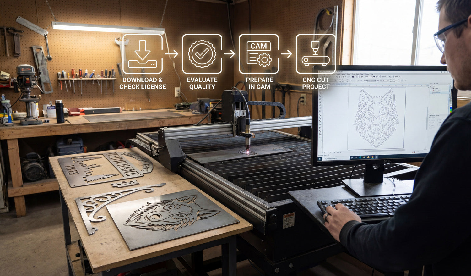
Free DXF files can help you test ideas, reduce design time, and launch new CNC projects faster—if you know how to find, check, and prepare them. What Are Free DXF Files? DXF (Drawing Exchange Format) files are 2D vector drawings made of lines, arcs, and curves. A “free DXF file” is simply a DXF design you can download at no cost from a website, forum, or community library. You can use these files as ready-made artwork, as a starting point to customize your own designs, or as practice material when you are learning how to run a CNC laser, plasma, router, or water-jet machine. Benefits of Using Free DXF Files in CNC Projects Free DXF files can be surprisingly powerful in your workshop if you use them the right way. Save design time: Skip the blank page and start from a design that is already drawn. Test your machine: Use free files to dial in speeds, power, kerf, and feeds on new materials. Prototype ideas: Try new product concepts without paying a designer or spending hours in CAD. Inspire new products: Study how good files are built and adapt layouts, proportions, and themes for your own designs. Learn the workflow: Practice importing, nesting, and cutting DXFs before you move to critical customer jobs. Where to Find Free DXF Files Safely You can find free DXF files in many places online, but quality and licensing vary a lot. Look for sources that: Focus specifically on CNC cutting and engraving (not just random clipart). Offer clear license information about personal and commercial use. Provide preview images so you can see what the final cut should look like. Have organized categories like animals, signs, panels, brackets, and so on. On your own site, you might maintain a dedicated section for free designs. For example, you can browse and download sample designs from a collection like Free DXF Files and test them on your laser, plasma, or router before investing in larger bundles. Always Check the License Before You Cut “Free” does not always mean “do anything you want.” Before you use a DXF file in a paid project or product line, read the license carefully. Personal use only: You can cut the design for yourself or as a gift, but not sell physical products made from it. Commercial use allowed: You can sell physical items made from the design (signs, wall art, brackets, etc.). No digital resale: In most cases you cannot resell, share, or repackage the DXF file itself as a digital product. Attribution requirements: Some licenses ask you to credit the designer or site. If the license is unclear, treat the file as personal-use only or choose a file from a source with clearly written terms. How to Evaluate the Quality of a Free DXF File Not every free DXF is cut-ready. Before you rely on a file, open it in your CAD or CAM software and do a quick quality check. Closed paths: Outer profiles and inner cutouts should be fully closed loops, not “almost closed” shapes with tiny gaps. No duplicate lines: Make sure there are no overlapping paths that could cause double cuts. Reasonable node count: Curves should be smooth with a sensible number of points, not thousands of tiny segments. Correct scale: Measure the design; it should import at a realistic size in mm or inches. Material-friendly detail: Thin bridges and tiny shapes should be big enough for your material thickness and kerf. If a file fails these tests, you can either clean it up or move on to a better DXF that saves you time instead of creating headaches. How to Prepare Free DXF Files for Your CNC Machine Even a good DXF file needs a little setup work before you cut it. Here is a simple workflow you can reuse: Import the DXF: Open the file in your CAD or CAM software. Confirm units and size: Measure a known feature and scale if needed so the part matches your target dimensions. Clean the geometry: Close open paths, delete duplicates, and remove stray points or tiny islands. Organize layers: Separate cut, engrave, and reference geometry into layers or colors if they are not already organized. Match detail to material: If the design is too detailed for your material or plasma kerf, simplify small features. Set toolpaths in CAM: Assign inside cuts, outside cuts, and engraving passes with proper speed, power, and kerf compensation. Run a test cut: Use scrap material to verify fit, edge quality, and overall look before running a full sheet or final product. Project Ideas Using Free DXF Files Free DXF files are perfect for learning, testing, and even launching simple product lines. Here are a few ideas: For Laser Cutters and Engravers Decorative wall art and panels. Custom keychains and ornaments. Nameplates, door signs, and small plaques. Engraved coasters, cutting boards, and gift items. For CNC Plasma Cutters Metal wall art and monograms. Fire pit panels and grills. Brackets, tabs, and gussets for fabrication. House number signs and yard art. For CNC Routers Wooden signs and 2.5D plaques. Simple furniture parts and brackets. Shelf supports, jigs, and fixtures. Inlay patterns and decorative panels. Organizing Your Free DXF Library As you download more free DXF files, a little organization will save you a lot of time later. Create folder groups like Laser, Plasma, and Router. Inside each, organize by category: Animals, Signs, Panels, Brackets, and so on. Use clear file names with type, size, and maybe material (for example, wolf_wall_art_600mm_steel.dxf). Keep notes on files you have already tested: best material, power, and speed settings. Over time, your “free DXF” folder can become a powerful design library that you reuse again and again. When to Move from Free DXF Files to Paid or Custom Designs Free DXF files are great, but they have limits—especially if you run a business. Originality: Popular free designs are used by many shops, so products may not feel unique. Depth of content: Free libraries are usually small compared to large commercial bundles. Support and consistency: Paid design sets are often more consistent in style, sizing, and cut quality. Once you know which styles sell or which categories your customers love, investing in high-quality DXF bundles or custom artwork can help you stand out and scale your CNC shop faster. Conclusion Free DXF files are a smart way to explore CNC projects, test new materials, and speed up your design process without extra cost. By choosing reputable sources, checking the license, cleaning the geometry, and organizing your downloads, you can turn “free files” into real value on your laser, plasma, router, or water-jet machine. Start small, build a clean library, and when you are ready, blend your favorite free designs with premium or custom DXF artwork to grow a strong CNC product line.
Why You Should Use DXF Files for Your CNC Laser Engraving Projects
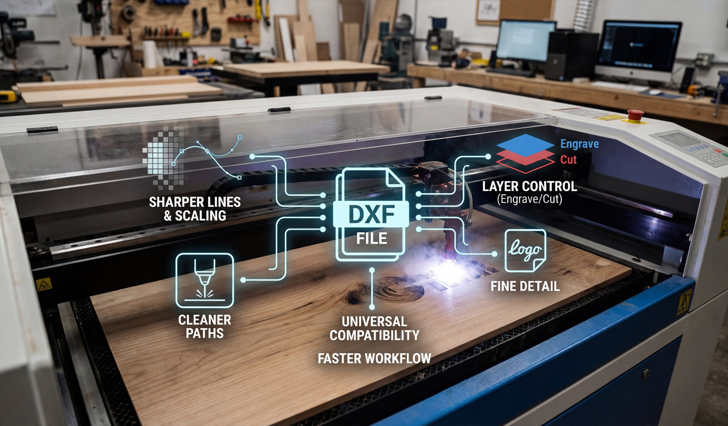
Using DXF files for your CNC laser engraving projects makes it easier to get crisp details, clean lines, and repeatable results while keeping your workflow simple and efficient. What Is a DXF File in Laser Engraving? DXF (Drawing Exchange Format) is a 2D vector file type that stores shapes as lines, arcs, and curves instead of pixels. For CNC laser engraving, this means your design is made of precise paths that the machine can follow directly, rather than a blurry image the software has to guess from. DXF files are supported by most CAD, graphics, and CAM programs, which makes them a natural “universal language” for CNC laser engravers. Reason 1: Sharper Lines and Unlimited Scaling One of the biggest advantages of using DXF files for laser engraving is that vector geometry never becomes pixelated or fuzzy. Crisp engravings: Lines and curves stay sharp at any size because they are defined by math, not pixels. Unlimited scaling: You can resize artwork for small keychains or large wall panels without losing quality. Consistent detail: Thin outlines, logos, and text stay clean and readable when designed correctly. If you have ever tried to engrave a low-resolution JPG and been disappointed with jagged edges, switching to DXF-based artwork is a big upgrade. Reason 2: Cleaner, Faster Engraving Paths DXF files describe exact paths, which helps your laser engraver move more efficiently. Smooth motion: Clean curves and polylines let the laser head move at a steady speed, improving engraving quality. Less back-and-forth: Vector paths can be optimized in CAM to reduce wasted travel and overlapping passes. Shorter job times: Efficient paths mean the laser spends more time engraving and less time repositioning. By starting with a clean DXF file, you give your CAM software the best possible data to generate compact, efficient engraving toolpaths. Reason 3: Easy Control Over Engrave vs Cut CNC laser projects often mix engraving and cutting in a single job—engrave a logo, then cut out the outer shape. DXF files make this easy to manage. Layers for operations: Put engraving lines on one layer and cut lines on another so they can use different power and speed settings. Color mapping: Many laser controllers let you assign different colors in the DXF to different power levels and passes. Safer workflow: Clear separation means you are less likely to accidentally cut where you only meant to engrave. With a well-organized DXF file, you can control every part of the design—deep cuts, light scoring, and filled engraving—using simple layer or color settings. Reason 4: Better Text, Logos, and Fine Detail Text and logos are at the heart of many laser engraving projects: nameplates, awards, signs, ID tags, and branded products. DXF files handle these elements very well. Editable vector text: You can adjust size, spacing, and fonts in CAD or vector software, then convert text to outlines for reliable engraving. Logo accuracy: Company logos and icons can be traced or drawn as vectors and stored in DXF format for long-term use. Fine line control: You can define stroke thickness and spacing in detail so small elements engrave cleanly without filling in. Because DXF files are based on vectors, even very small text and thin lines can remain readable when engraved at the right scale. Reason 5: Consistent Results Across Different Lasers As your workshop grows, you may use different brands or sizes of CNC laser engravers. DXF files help keep your designs portable and consistent. Universal format: Most laser software can import DXF, regardless of machine brand. Same artwork, different settings: You can reuse the same DXF file and simply adjust speed, power, and frequency for each machine or material. Easier outsourcing: If you send work to another shop, DXF files are widely accepted and easy to use. This portability means your artwork library stays useful even if you upgrade machines or add new equipment later. Reason 6: Flexible Design Edits and Personalization Many CNC laser engraving projects are customized: names, dates, serial numbers, or personalized messages. DXF-based workflows make these changes simple. Quick text changes: Edit names or messages directly in your CAD/vector program and re-export the DXF. Modular layouts: Keep fixed artwork (logos, borders) as one DXF and swap in different nameplates or text blocks as needed. Batch personalization: Set up templates where only a small part of the DXF changes from job to job. This approach is ideal for engraving businesses that produce repeat designs with unique customer details. Reason 7: Smaller File Sizes and Easier Storage Complex image engravings can create very large raster files. DXF files, being vector-based, stay relatively compact even with detailed designs. Efficient storage: Large design libraries take up less space when stored as DXF. Faster loading: Laser software can often load vector DXFs faster than high-resolution bitmaps. Simple backups: Smaller files are easier to back up and sync between computers or cloud storage. Over time, a well-organized DXF library becomes a high-value asset that is easy to maintain and move between systems. How DXF Files Fit into a Typical Laser Engraving Workflow Here is how DXF files usually plug into a CNC laser engraving process: Create or edit artwork: Design your layout in CAD or vector software (text, logos, borders, frames). Organize layers and colors: Separate engraving and cutting paths into different layers or colors. Export as DXF: Save or export the design in DXF format. Import into laser software: Open the DXF, assign power/speed settings to each layer or color, and position the design on the material size. Simulate and preview: Check the order of operations and verify scale. Engrave and cut: Run a test on scrap material if needed, then engrave the final piece. Common Mistakes When Not Using DXF (or Using It Poorly) Understanding what can go wrong helps you see why clean DXF files are valuable: Low-resolution images: Engraving small JPGs can lead to fuzzy edges and unreadable text. Unscaled artwork: Designs imported at the wrong size cause cramped layouts or wasted space. No layer separation: Cutting and engraving lines mixed together increase setup time and risk mistakes. Messy vectors: Auto-traced files with too many nodes can slow down engraving or cause jittery motion. By investing a little time to prepare clean DXF artwork, you avoid these problems and get more consistent results. Checklist: Is Your DXF Ready for CNC Laser Engraving? Before sending a job to your laser engraver, run through this quick DXF checklist: ✔ The design is vector-based, not just a low-res image. ✔ All important outlines and text are converted to curves and scale correctly. ✔ Engraving and cutting paths are on separate layers or colors. ✔ Detail level matches your material and lens (no micro details that will burn away). ✔ There are no duplicate or overlapping lines where you only want a single pass. ✔ Text, logos, and fine elements look clear at the final size you plan to engrave. Conclusion DXF files are one of the best foundations you can use for CNC laser engraving projects. They give you crisp lines, infinite scaling, clean engraving paths, and flexible control over cutting versus engraving—all in a format that works across most CAD, CAM, and laser systems. Whether you are engraving custom gifts, branded products, signs, or industrial labels, building your workflow around DXF files will make your jobs faster, cleaner, and more consistent on every CNC laser engraver you use.
Using DXF Files for Complex CNC Milling Projects
Using DXF files for complex CNC milling projects gives you a clean way to define profiles, pockets, and critical 2D geometry so your CAM software can generate accurate toolpaths for multi-step, multi-setup machining. How DXF Files Fit into Complex CNC Milling Work CNC milling is more than simple outlines. Real projects often include: Multiple pockets at different depths. Step faces and 2.5D contours. Bolt patterns, slots, and precision holes. Parts that require multi-side machining (top, bottom, and edges). DXF (Drawing Exchange Format) files are ideal for describing the 2D geometry behind those features—profiles, boundaries, and reference curves that your CAM system uses to drive roughing and finishing toolpaths. DXF vs 3D Models in CNC Milling Many complex milling projects use both 3D models and DXF files together. 3D models (STEP, IGES, etc.): Define full solid shapes and surfaces for complex 3D machining. DXF files: Define precise 2D outlines, pockets, and hole patterns for profiling and 2.5D operations. Even if you work from a full 3D model, exporting critical views as DXF—for example, the top profile or bolt circle—can make it easier to create and control specific milling operations in CAM. Planning Complex Milling Projects with DXF Geometry Before you start drawing or importing DXF files, think through the overall milling strategy. Setup plan: How many setups will you need (top only, top and bottom, or multiple sides)? Zero and origin: Where will your work coordinate system (WCS) be? Corner, center, or a feature? Feature groups: Which features are roughing only, which are precision, and which can be cut in a single operation? Tools and holders: What tool diameters and lengths will be used for each area? Once you have a plan, you can build or clean DXF geometry that directly supports that strategy instead of fighting against it. Creating DXF Files for Profiles and Pockets In complex CNC milling, DXF files are especially useful for defining: Outer profiles: The final outside shape of the part as viewed from the top. Inner pockets: Closed contours that mark where material should be removed to a certain depth. Bosses and islands: Areas that should stay at a higher level inside a pocket. Slots and keyways: Long, narrow cutouts used for mechanical function. Each of these can be drawn or exported as clean, closed 2D loops that your CAM software recognizes as milling regions. Layering DXF Geometry for Complex Operations Using layers in your DXF file makes it much easier to handle multiple depths, tools, and strategies. Place outer profiles on one layer (for example, PROFILE_OUTSIDE). Place pockets at depth 1 on another layer (for example, POCKET_Z-5). Place deeper pockets or step faces on separate layers (for example, POCKET_Z-10). Place drill holes and bolt circles on a HOLES layer. Use a REFERENCE layer for centerlines, datums, and construction geometry that should not be cut. When you import the DXF into CAM, you can map each layer to a different operation and depth, which speeds up programming and reduces mistakes. Designing DXF Geometry with Tool Diameter and Corner Radii in Mind CNC milling tools are round, so your DXF design must respect tool diameter and minimum radius limits. Inside corners: Use fillets with a radius at least equal to (and often slightly larger than) the smallest tool radius you plan to use. Slots and pockets: Make sure the width is comfortably larger than your tool diameter so the cutter has room to clear chips. Sharp transitions: For precision fits, consider adding small relief pockets or “breakout” radii where mating parts need clearance. Drawing these features correctly in DXF reduces the need to “cheat” toolpaths in CAM and helps you hold tolerances more easily. Using DXF for Multi-Setup and Multi-Side Milling Complex milling jobs often require machining from more than one side. DXF files can help you manage this. Top view DXF: Defines top profiles, pockets, and drilling layouts. Bottom view DXF: Represents flip-side operations, such as back-side pockets and relief cuts. Side view DXFs: For parts that need machining on the sides, simple 2D side profiles can guide slotting or step cuts. By developing a set of DXF views tied to your setup plan and workholding, you can keep each operation clear and reduce alignment errors between sides. DXF-Based Hole Patterns and Bolt Circles Complex CNC milling projects often include many holes and bolt patterns that must align perfectly with other parts. Use DXF to define exact hole locations based on true dimensions and references. Draw bolt circles with centerlines and a reference diameter so your CAM software can apply drilling or circular pocketing easily. Keep hole types (clearance, tap, dowel) organized on separate layers if they require different tools or cycles. Clear hole geometry in DXF allows CAM to generate drilling, reaming, and countersink operations quickly and consistently. Preparing DXF Files for Rest Machining and Finishing Passes On complex parts, you may rough with a larger tool and finish with a smaller one. DXF boundaries can drive these steps. Define rest machining regions as DXF contours where the larger tool cannot reach (tight corners and small pockets). Use separate layers for finishing boundaries so CAM can apply light, precise finishing passes only where needed. For critical surfaces, create offset boundaries that represent specific finish zones or tolerance areas. This gives you fine control over where extra machining effort is spent, improving both surface finish and cycle time on complex parts. Ensuring DXF Precision: Tolerances and Scaling For complex milling, dimensional accuracy is critical. Your DXF must reflect true sizes and tolerances. Work in the correct units (mm or inches) and double-check overall dimensions. Use precise dimensions in CAD and avoid rounding key features without a reason. Include reference dimensions or a known-length line (for example, exactly 100 mm) to verify scale inside CAM. Document any intentional offsets (for press fits, sliding fits, or adhesive space) so CAM programmers know why the DXF differs from nominal print values. A clean, accurately scaled DXF reduces guesswork and helps you hit target tolerances on the real part. Common DXF Mistakes in Complex CNC Milling Even advanced users run into issues when preparing DXF files for complex projects. Watch out for: Open contours: Profiles or pockets that are not fully closed, confusing CAM’s pocketing and profiling algorithms. Duplicate lines: Overlapping geometry that causes extra passes and poor surface finish. Unclear layer names: Layers called “Layer1” or “default” that do not explain their purpose. Ignoring tool access: Tight features that a real tool and holder cannot reach without collision. No datum references: DXFs that lack clear origin points or datums for aligning multi-setup operations. Building a Reusable DXF Library for Complex Milling Over time, your best DXF files become building blocks for future projects. Save proven pocket shapes, joints, bolt circles, and fixtures as reusable DXF components. Organize them by category—structural, decorative, fixture, etc.—for quick access. Document recommended tools and feeds/speeds that pair well with each standard feature. Reuse and adapt existing DXF geometry for new projects instead of starting from zero. This approach speeds up CAM programming, improves consistency between jobs, and helps new team members follow established milling practices. Conclusion Using DXF files for complex CNC milling projects is a powerful way to control profiles, pockets, hole patterns, and multi-setup operations with precision. By designing clean, layered 2D geometry that respects tool diameter, corner radii, and real-world tolerances, you give your CAM software a strong foundation for efficient toolpaths. Over time, a well-organized DXF library becomes a key asset—helping you program faster, hold tighter tolerances, and deliver complex milled parts with confidence and repeatability.

How DXF Files Can Improve the Efficiency of Your CNC Plasma Cutter
Using well-prepared DXF files is one of the easiest ways to boost the efficiency of your CNC plasma cutter, cut more parts per hour, and get better results from the same machine. Why DXF Files Matter So Much for CNC Plasma Cutting A CNC plasma cutter follows paths. If those paths are messy, broken, or inefficient, your machine wastes time and consumables. DXF (Drawing Exchange Format) files store clean vector geometry—lines, arcs, and curves—that plasma CAM software can turn into fast, reliable toolpaths. With good DXF files, you can: Reduce total cutting time per sheet. Lower pierce counts and arc-on time. Use consumables more efficiently. Get more repeatable, production-ready parts. Benefit 1: Cleaner Toolpaths and Faster Motion When a DXF file is clean, your CAM software can generate smooth, continuous toolpaths. That has a direct impact on plasma cutting speed. Continuous contours: Long, uninterrupted lines and arcs keep the torch moving at a steady speed. Fewer stops and starts: Reduced lifting and repositioning means less non-cutting time. Better acceleration and deceleration: Smooth geometry lets the machine follow paths at higher feed rates without shaking. The result: shorter cycle times and more parts cut per shift, without touching your speed and amperage settings. Benefit 2: Fewer Duplicate Lines and Double Cuts Duplicate lines are a common hidden problem in DXF files. On a plasma cutter, double cutting the same path wastes time and overheats the material. Extra arc-on time: Cutting a contour twice increases wear on consumables. Wider kerf and rough edges: Double passes can widen the cut and leave ugly edges. More dross and warping: Extra heat can warp thin material and create more cleanup work. DXF files that have been cleaned with “remove duplicates” tools eliminate this problem, allowing the torch to make a single, efficient pass on every contour. Benefit 3: Optimized Piercing and Cut Ordering Pierces are expensive in plasma cutting. They consume consumables, generate heat, and slow down each job. Good DXF files help your CAM software minimize pierces. Closed, continuous profiles: Allow the CAM system to combine segments into a single cut with one pierce. Logical internal features: Clean inner cutouts help the software cut holes first, then outer profiles, with the least number of pierces. Shared edges (common-line cutting): In some jobs, parts can share edges so a single cut separates two parts. When your DXF geometry is organized well, the software can automatically apply smarter pierce and cut-order strategies that save real time on the table. Benefit 4: Better Nesting and Material Utilization DXF files with accurate, closed outlines are much easier to nest efficiently on a sheet. Tighter nesting: Clean contours allow parts to be placed closer together without overlaps. Less scrap: Better material utilization means you buy fewer plates for the same number of parts. Simpler layout: Consistent geometry and size variants help you build standard nests for common jobs. More parts per plate and fewer offcuts directly improve the overall efficiency and profitability of your plasma cutting operation. Benefit 5: Correct Kerf Compensation and Tolerances Kerf width is a big factor in plasma cutting. Good DXF files are designed with kerf and tolerances in mind, which reduces rework and scrap. Proper slot and hole sizes: Features are drawn with the expectation that kerf compensation will be applied in CAM. Consistent dimensions: Straight, clean vectors allow the CAM software to offset paths accurately. Less trial and error: When the base geometry is reliable, you do not have to “fudge” dimensions every time. Parts that come off the table fitting correctly the first time save shop time and keep your plasma cutter focused on production, not rework. Benefit 6: Layer Control for Marking and Cutting Many CNC plasma systems can mark, scribe, or lightly etch as well as cut. DXF files that use layers effectively make this easy to manage. One layer for through cuts (outer profiles and holes). Another layer for part numbers, bend lines, or reference marks that are etched instead of cut through. A separate layer for construction geometry that the machine should ignore. Layered DXF files reduce setup time and help you add useful information to parts without slowing down production. Benefit 7: Faster Setup with Ready-to-Use DXF Libraries When you build or buy a library of high-quality, plasma-ready DXF files, your setup time drops dramatically. Repeat jobs: Common brackets, gussets, and tabs can be loaded and nested in minutes. Product lines: Standardized part families (different sizes and thicknesses) share similar DXF geometry. Less programming: Operators spend less time drawing and more time cutting. A strong DXF library turns your CNC plasma cutter into a fast “production engine” instead of a machine that is constantly waiting for drawings. How to Prepare DXF Files for Maximum Plasma Efficiency To get all these benefits, your DXF files should follow a few simple best practices: Clean geometry: Close all paths, remove duplicates, and simplify overly dense curves. Plasma-ready detail: Avoid tiny features below your kerf and material strength limits. Smart layering: Separate cut, mark, and reference geometry. Correct scale and units: Confirm real-world size before generating toolpaths. Standardization: Use consistent slot widths, hole sizes, and tab designs across your parts. Quick DXF Efficiency Checklist for CNC Plasma Cutters Before you send a DXF job to your plasma cutter, ask yourself: ✔ Are all outlines closed and free of gaps? ✔ Have I removed duplicate and overlapping lines? ✔ Does the design avoid micro details that plasma cannot hold? ✔ Are pierces minimized through continuous contours and smart nesting? ✔ Are layers organized for cutting versus marking? ✔ Has this DXF (or a previous version) been cut and adjusted for kerf and fit? Conclusion DXF files are more than just a way to store 2D drawings—they are a key lever for improving the efficiency of your CNC plasma cutter. Clean, well-organized DXF geometry leads to faster toolpaths, fewer pierces, better nests, and parts that fit right the first time. By investing a little effort into preparing and standardizing your DXF files, you turn your plasma cutter into a faster, more profitable production tool without changing the hardware at all.
What to Look for in a Good DXF File for CNC Laser Cutting
A good DXF file for CNC laser cutting should be clean, closed, correctly scaled, and designed with real laser limits in mind; anything less will cost you time, money, and material. Why DXF File Quality Matters for Laser Cutting Your laser cutter is only as good as the file you feed it. Even with a powerful machine and a good lens, a messy DXF can cause: Jagged or rough edges. Small details burning away or falling out. Double cuts and heat marks from overlapping lines. Wrong part sizes due to unit or scale mistakes. Extra setup time fixing geometry instead of cutting. When you know what to look for in a DXF file, you can quickly tell if a design is laser-ready or if it needs cleanup before you hit “Start.” 1. Clean, Continuous Vector Geometry A strong DXF file is built from clean vector paths, not random segments and noise. Lines, arcs, and polylines: The design should use proper vector entities, not thousands of tiny line fragments. Smooth curves: Arcs and curves should look smooth at any zoom level, without “stair-stepping.” No broken edges: Profiles should flow logically without strange kinks or corners where there should be smooth curves. If the design was auto-traced from a low-resolution image, you will often see noisy geometry and too many nodes. That is a warning sign of trouble on the laser. 2. All Cut Paths Are Fully Closed For laser cutting, most outer borders and inner cutouts must be closed loops. Open shapes can confuse the software and cause missing cuts or strange toolpaths. Outer profiles: The main shape of the part or artwork should be one continuous loop. Inner cutouts: Holes, letters, and internal windows must also be closed paths. No micro gaps: Tiny gaps between endpoints can be hard to see, but they break the loop. When inspecting a DXF, zoom in on corners and intersections. If you see lines that “almost” meet, the file needs repair before it is truly laser-ready. 3. No Duplicate or Overlapping Lines Duplicate lines are a silent killer in laser cutting. They cause the laser to cut the same path twice, which: Adds extra heat and burn marks. Slows down your job. Can cause narrow bridges or details to fall out. A good DXF file should: Have only one line for each cut path. Use clean, non-overlapping outlines for each shape. Avoid stacked borders (no “double outlines” sitting on top of each other). Many CAD programs offer a “remove duplicates” or “overkill” command. If you are not sure a DXF is clean, run this check before importing into your laser software. 4. Correct Units and Realistic Scale A good DXF will open at the expected size without guesswork. File creators should design with clear units and realistic dimensions. Units declared: The design should be drawn in either millimeters or inches and documented as such. Reasonable size: A wall art DXF that imports as 3 mm wide or 30 meters wide is clearly wrong. Check with a known feature: Designs with a known dimension (for example, 100 mm width) are easier to verify. When you open a DXF for laser cutting, always measure a key feature. If the size is off by a factor of 10 or 25.4, you have a unit or scale problem to fix. 5. Laser-Friendly Detail Level Not all detail that looks good on screen will survive real laser cutting. A good DXF balances visual complexity with what a laser can actually produce in your chosen material. Minimum feature size: Thin bridges, narrow gaps, and tiny holes must be wider than your laser kerf and strong enough for handling. Material thickness ready: Details that work in 3 mm steel might be too fragile in 1 mm stainless or thin wood. Readable text: Letters should be large enough and thick enough to stay legible after cutting and finishing. Good DXF designers think about material and laser limitations up front. If the file is packed with ultra-thin lines and micro cutouts, expect problems unless you scale it up or simplify. 6. Smart Use of Layers and Colors High-quality DXF files often use layers (and sometimes colors) to separate different operations. Cut vs engrave: Outlines for through-cuts are on one layer; engraving or scoring paths are on another. Reference geometry: Construction lines, dimensions, and notes are placed on a non-cutting layer. Optional features: Some designs include alternate options or cut levels on separate layers that you can turn on or off. This structure saves time when you import the file into laser software. You can easily map each layer to different power, speed, or line type settings instead of selecting shapes one by one. 7. Reasonable Node Count and Smooth Paths A DXF full of thousands of tiny nodes slows the machine and can create jittery cuts. A good file keeps node count under control. Simplified curves: Paths are smooth and use just enough nodes to describe the shape accurately. No noisy outlines: Auto-traced artwork should be cleaned up so outlines do not wiggle or vibrate visually. Efficient motion: Fewer nodes means the laser head can move at more consistent speed, improving edge quality. When evaluating a DXF, select a curve and look at its control points. If you see a dense forest of nodes everywhere, the design will likely benefit from curve optimization. 8. Logical Origins and Positioning Good DXF files are easy to place on the laser bed and nest with other parts. Clear origin: The design is placed near the 0,0 origin instead of being miles away from the coordinate system. Centered or aligned: Parts are arranged logically, often centered or aligned to an axis for easy rotation and positioning. No random offsets: The file does not open with the geometry far off to one corner of the view. Clean positioning makes it faster to drop the design into your material layout, especially if you are nesting multiple DXF files on the same sheet. 9. Tested and Proven Designs The best DXF files for laser cutting are not just “pretty” drawings; they are designs that have been cut and refined based on real-world results. Cut-tested: The file’s creator has actually cut the design and fixed weak areas or problem details. Stable bridges: Hanging elements, letters, and small features are supported by well-placed bridges or tabs. Good fit: For mechanical parts, holes and slots have been adjusted for kerf and material tolerances. If you are building your own library, consider taking notes every time you cut a new DXF: which details worked, which failed, and what changes improved the next version. 10. Legible, Connected Text and Lettering Text is one of the most common problem areas in laser DXF files. A good file handles lettering correctly. Stencils for inner islands: Letters like A, O, P, R, and D need bridges so the inner pieces do not fall out. Enough stroke width: Fonts are thick enough to cut cleanly and survive handling. Converted to curves: Text is converted to vectors (outlines) rather than relying on missing fonts on another computer. When you open a DXF, zoom in on the text. If inner islands are floating with no support, the design is not truly laser-ready. 11. No Unwanted Fills, Hatches, or Images Laser cutters care about paths, not fills or bitmaps. A good DXF keeps the file clean. No bitmap images: JPG or PNG images are not embedded as “background art” inside the DXF. No complex hatches: Hatch patterns may look nice in CAD but can confuse CAM software or slow it down. Vector-only: All cutting and engraving elements are vector paths that the laser can follow. If a DXF is full of shading, fills, and non-vector elements, expect to do extra cleanup before it will work correctly on the laser. Quick Checklist: Is This DXF Good for CNC Laser Cutting? Before you send a job to your laser, use this short checklist: ✔ All cut paths are closed loops (no gaps). ✔ There are no duplicate or overlapping lines. ✔ The size and units are correct and realistic. ✔ Detail level fits your material thickness and laser kerf. ✔ Layers clearly separate cut, engrave, and reference geometry. ✔ Curves have a reasonable node count and look smooth. ✔ Text uses stencil-friendly, connected lettering where needed. ✔ There are no unnecessary fills, hatches, or bitmap images. Conclusion A good DXF file for CNC laser cutting is more than just a nice drawing; it is a clean, closed, scalable set of vector paths designed with real laser behavior in mind. When you know what to look for—closed geometry, no duplicates, correct scale, laser-friendly details, smart layering, and tested design choices—you can quickly judge whether a file is ready for the machine or needs work. Investing a little time in checking and improving your DXF files pays off in faster setups, cleaner cuts, less scrap, and more reliable results on every laser job you run.
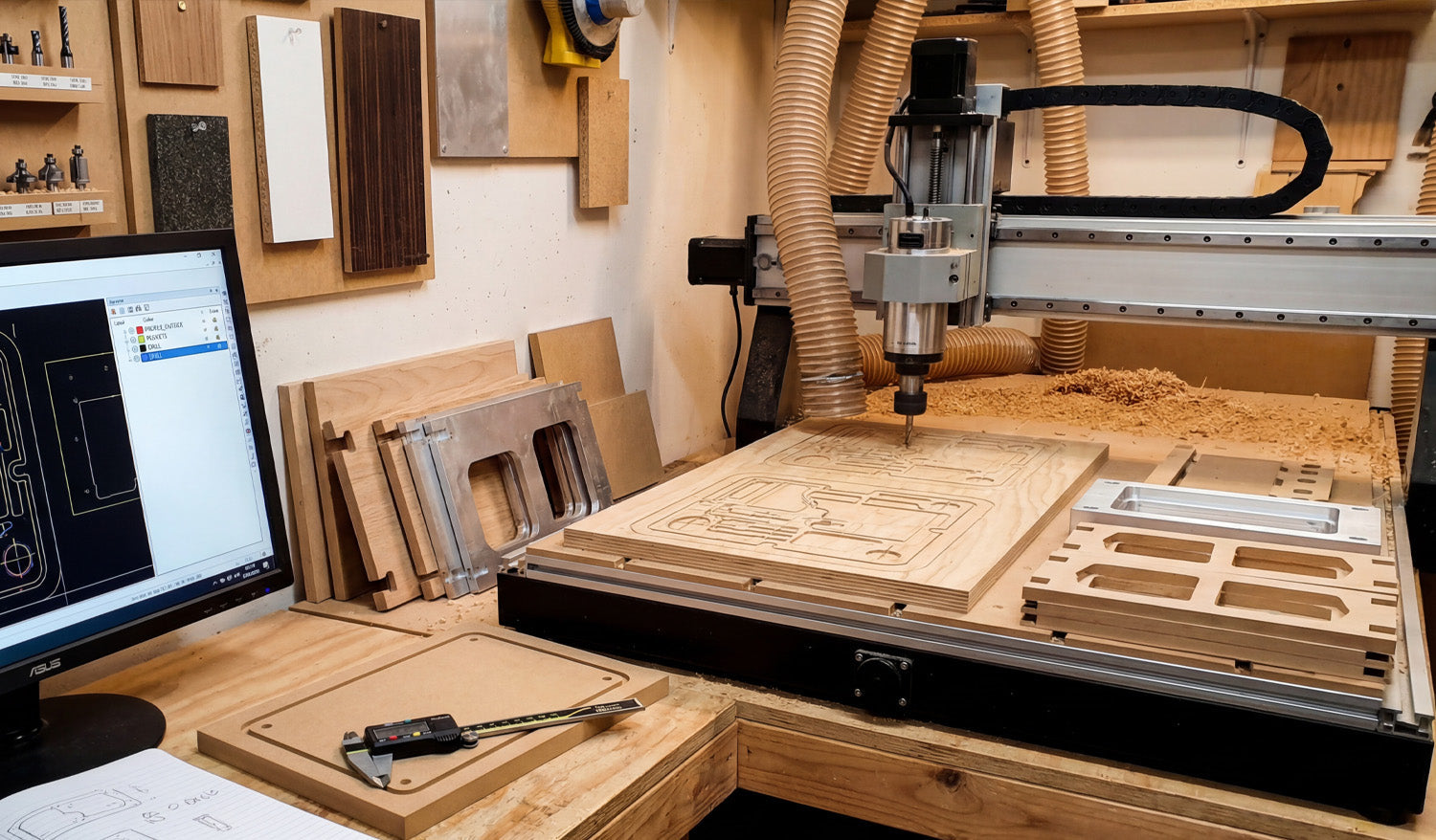
DXF Files for CNC Routing: How to Design for Precision and Efficiency
DXF files are a perfect match for CNC routing because they store precise 2D geometry, let you design around tool diameter and material limits, and help you cut parts with both high precision and high efficiency. What Makes CNC Routing Different from Other CNC Cutting? CNC routers are usually used on wood, MDF, plywood, plastics, foam, and sometimes aluminum or other soft metals. Unlike lasers or plasma cutters, a router removes material with a rotating bit, not a beam. That means: The tool has a fixed diameter (for example, 3 mm or 1/4 inch). Inside corners will always have a radius based on that diameter. You often need multiple passes for deep cuts. Hold-down, tabs, and material support are critical to avoid parts moving. Your DXF design must respect these realities if you want precise parts and fast cycle times on a router. Why DXF Files Work So Well for CNC Routers DXF (Drawing Exchange Format) files store lines, arcs, and curves as exact vectors, which is exactly what a CNC router needs for toolpaths. Accurate outlines: Router CAM software can follow DXF curves to create smooth profile cuts and pockets. Flexible scaling: You can resize designs for different router beds or product sizes without losing quality. Layer organization: Different depths, operations, and tools can be separated on layers for easier CAM setup. Wide compatibility: Almost every CAD and CAM package used in routing can import and export DXF files. Step 1: Plan Your Part for Router-Friendly Cutting Before drawing anything, think about how your part will be cut on a CNC router. Material: MDF, plywood, hardwood, plastic, etc.—each has a safe minimum feature size and ideal feed rates. Thickness: Thicker materials usually need more passes and stronger tabs. Tool size: A 6 mm or 1/4 inch bit is common; very small tools cut slower and are more fragile. Machine bed size: Make sure your design fits with enough margin for clamps or vacuum zones. Assembly needs: If parts must fit together (slots, tenons, pockets), design those features with real tolerances. Clear planning helps you avoid impossible inside corners, weak tabs, and other problems that waste time later. Step 2: Set Up Your DXF Drawing for Precision Good DXF routing starts with a clean drawing environment in your CAD or vector software. Choose units—millimeters or inches—and stick to them for the entire design. Turn on snap options (endpoints, midpoints, intersections) to keep geometry aligned. Create layers such as PROFILE_OUTSIDE, PROFILE_INSIDE, POCKETS, DRILL, and REFERENCE. Use line colors or styles to quickly see which geometry belongs to which operation. This structure makes it easier to keep your DXF precise and to map layers to operations in your CAM software later. Step 3: Design with Tool Diameter and Inside Corners in Mind Router bits are round, so your DXF design must account for that in all internal geometries. Inside corners: A router cannot cut a perfectly sharp inside corner. Use fillets with a radius at least equal to the tool radius (ideally slightly larger). Slots and mortises: Make slot widths slightly larger than the mating tenon or tab, and consider adding “dogbone” or “T-bone” fillets so square parts can fit into routed corners. Holes: Small holes should match standard drill or bit sizes. For very small holes, consider drilling instead of profiling. Thin walls and bridges: Keep thin sections wider than 2–3× the tool diameter so they do not break during cutting. Designing around tool diameter up front prevents fit issues and lets you cut faster without overloading the bit. Step 4: Control Tabs, Bridges, and Hold-Down Because a router physically pushes on the material, parts can move once they are fully cut out. Your DXF should anticipate this with tab-friendly geometry. Plan tab locations along straight edges or less-visible areas of the part outline. Avoid putting tabs on tight inside corners or small decorative areas where they are hard to sand off. Ensure there is enough edge length to place several tabs on larger parts for stability. For small parts, consider grouping them within a larger frame or using additional bridges so they do not fly loose. When your DXF has clean, continuous outer contours, CAM software can automatically place tabs where they make the most sense. Step 5: Optimize Contours for Efficient Toolpaths Efficient router toolpaths start with efficient DXF geometry. Use polylines: Combine separate segments into single polylines for smoother motion. Remove duplicates: Delete overlapping lines that could cause double cuts and burn marks. Simplify curves: Reduce unnecessary nodes while keeping the shape true so the router can maintain consistent feed rates. Close all profiles: Make sure outer and inner profiles are closed loops so CAM can recognize pockets and cut directions correctly. Clean geometry helps your router maintain speed, reduces tool wear, and improves edge finish. Step 6: Layer Strategy for Multi-Depth and Multi-Tool Jobs Many CNC routing jobs use more than one depth or tool. DXF layers can make this much easier to manage. Use one layer for through cuts (full depth) and another for pockets (partial depth). Separate engraving or V-carve lines from standard profile cuts. If you plan to use multiple tools (for example, a large roughing bit and a small finishing bit), place geometry for each tool on its own layer. Keep construction geometry (guides, centerlines, dimensions) on a reference layer that will not be exported or used for cutting. When you import the DXF into CAM, you can quickly assign each layer to the right tool, depth, and operation without manually selecting hundreds of elements. Step 7: Check and Export a Clean DXF for Routing Before exporting, do a final quality check on your DXF file. Measure overall dimensions and critical features (slots, tenons, holes) to confirm they match your design intent. Check that inside corners have appropriate radii or dogbone cutouts. Look for stray points, tiny islands, or small gaps between segments. Confirm layers are named and organized consistently. Then export your drawing: Use Save As or Export and choose DXF. Select a DXF version your router CAM software prefers (commonly R12 or R14). Give the file a descriptive name like cabinet_side_MDF18mm_800mm_v1.dxf. Common Design Mistakes to Avoid in CNC Routing DXFs Even experienced users fall into a few common traps. Avoid these to keep your routing precise and efficient: Square inside corners: Designing perfect 90° inside corners without clearance for the round bit, causing poor fit. Overly thin features: Creating very narrow walls or tabs that chip or break during cutting. Too much tiny detail: Adding small decorative features that slow down cutting and are hard to sand or finish. No allowance for glue or finish: Forgetting to leave enough tolerance in joints that will later be glued, painted, or coated. Ignoring grain direction: For wood, not considering grain orientation where strength or appearance matters. Practical Tips for Precision and Efficiency Test joints at full scale: Cut a small sample of a slot and tenon before committing to a full sheet. Standardize key dimensions: Reuse the same slot widths, tab sizes, and hole diameters across designs to simplify tooling and setup. Use copy and mirror: For symmetrical parts, draw half with precision and then mirror it to avoid small asymmetries. Document best settings: Save notes on feed, speed, and depth of cut that work well with specific materials and bit sizes. Build a reusable library: Keep a library of proven DXF parts—brackets, joints, patterns—that you can drop into new projects. Conclusion DXF files for CNC routing are powerful tools when they are designed with precision and efficiency in mind. By planning around tool diameter, using clean and organized geometry, controlling tabs and hold-down, and separating operations into clear layers, you give your router CAM software exactly what it needs to generate fast, accurate toolpaths. The result is a smoother workflow, better-fitting parts, less scrap, and a growing design library that you can reuse across countless routing projects.

