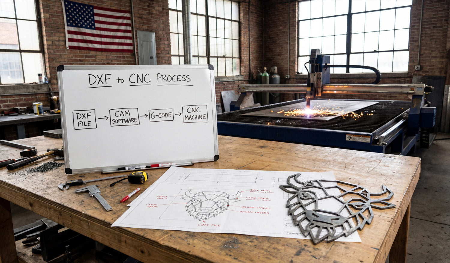
Converting DXF files into CNC-ready files is all about taking clean 2D geometry and turning it into the right toolpaths and machine code for your laser, plasma, router, or milling machine.
DXF vs CNC-Ready Files: What’s the Difference?
A DXF (Drawing Exchange Format) file is a 2D vector drawing: lines, arcs, and curves. It describes the shape of your part or artwork, but it does not tell a CNC machine how fast to move, how deep to cut, or what order to follow.
CNC-ready files, on the other hand, are machine instructions. They are usually:
-
G-code files (for routers, mills, some lasers and plasmas) with extensions like
.nc,.tap, or.gcode. - Controller-specific job files for branded laser and plasma systems.
The goal is simple: start with a clean DXF, process it in CAM or controller software, and export the correct CNC-ready file for your specific machine.
Step 1: Clean and Prepare Your DXF File
Before you convert anything, make sure your DXF file is in good shape. A clean DXF makes every later step easier.
- Check units and scale: Confirm whether the design is in millimeters or inches and verify a key dimension.
- Close all profiles: Outer shapes and inner cutouts should be closed loops with no small gaps.
- Remove duplicate lines: Delete overlapping or stacked paths so the machine does not cut the same line twice.
- Simplify curves: Reduce unnecessary nodes on curves for smoother motion.
- Use layers: Separate cut, engrave, score, pockets, and reference geometry onto different layers if possible.
Step 2: Choose the Right CAM or Controller Software
DXF files are neutral. To turn them into CNC-ready files, you need CAM (Computer-Aided Manufacturing) or machine control software that understands both DXF and your machine.
- Laser cutters: Often use built-in controller software that imports DXF and lets you set power and speed per layer/color.
- Plasma tables: Use CAM software to create lead-ins, pierces, and kerf-compensated toolpaths from DXF geometry.
- CNC routers: Use CAD/CAM packages that can turn DXF profiles into 2D/2.5D toolpaths (profile, pocket, drill).
- CNC mills: Use CAM systems that support contouring, pockets, drilling cycles, and multiple coordinate systems.
Pick the software that matches your machine brand, control type, and the complexity of your projects.
Step 3: Import the DXF and Confirm Geometry
Once you open the DXF in CAM or controller software, verify that everything came in correctly.
- Check the overall size and compare it to your design plan.
- Confirm that layers and colors are still present and readable.
- Look for broken contours, tiny gaps, or missing shapes that might not have imported correctly.
- Delete any dimensions or reference geometry that you do not want the CNC to follow.
Step 4: Assign Operations to Geometry
Now tell the software what each line or shape in the DXF is supposed to do.
- Profile cuts: Outside outlines and internal cutouts that should go all the way through.
- Pockets: Areas where you want to remove material to a certain depth (router and mill).
- Engraving / scoring: Light surface lines for logos, text, and guides.
- Drilling: Holes that are better done with drill cycles than with profile cuts.
Many CAM packages let you select by layer or color, which makes this step much faster when your DXF is well organized.
Step 5: Apply Machine-Specific Settings
This is where you convert neutral DXF geometry into real-world machining instructions. Each machine type needs different settings.
For CNC Laser Cutting
- Set power, speed, and frequency for each layer (cut, engrave, score).
- Choose cut order (inner shapes first, outer profiles last).
- Decide between vector-only (lines and curves) and raster engraving for fills.
- Apply kerf compensation if supported, or adjust dimensions in the DXF for critical fits.
For CNC Plasma Cutting
- Set material type and thickness in the CAM software.
- Define kerf width, lead-ins, and lead-outs for each contour.
- Configure pierce height, cut height, and pierce delay for clean starts.
- Optimize cut order to reduce warping and minimize pierces.
For CNC Routers
- Choose the right tool diameter, flute count, and material in the tool library.
- Set spindle speed, feed rate, and plunge rate based on material and tool.
- Define cut strategies: profile inside / outside, pocketing, and drilling.
- Add tabs to hold parts in place during cutting.
- Apply stepdown (depth per pass) and stepover for efficient removal.
For CNC Milling Machines
- Set up your work coordinate system (WCS) and origin (corner, center, or feature).
- Assign roughing and finishing toolpaths to contours and pockets.
- Use correct drilling cycles (peck, tap, ream) for hole geometry.
- Define depths, stepdowns, feeds, and speeds with respect to tool and material.
Step 6: Generate Toolpaths and Simulate
Once operations and settings are in place, tell the CAM software to create toolpaths.
- Check that all outer edges are cut from the correct side (inside vs outside compensation).
- Verify that all holes and pockets are included and at the correct depth.
- Run a simulation to see how the tool moves and how long the job will take.
- Look for collisions, air cuts, or strange moves that suggest a setup problem.
Simulation is your chance to catch mistakes before they damage material or tools.
Step 7: Post-Process to Create CNC-Ready Files
Post-processing is the final step that converts toolpaths into the exact format your machine controller expects.
- Choose the correct post-processor for your machine (for example, GRBL, Mach3, Fanuc, or a brand-specific post).
- Export the program with a clear name, such as partname_machine_material_v1.nc.
- Review the generated code if you are comfortable reading G-code (optional but helpful).
Now you have a CNC-ready file that your machine can run, generated from your original DXF design.
Step 8: Run Test Cuts and Refine
For new designs or new materials, always test before full production.
- Run the program on scrap or offcut material first.
- Check fit, edge quality, and detail (especially holes, tabs, and thin features).
- Adjust feeds, speeds, power, or kerf compensation as needed.
- Update your CAM setup and re-post the CNC-ready file once you are satisfied.
Save your successful DXF + CAM + post-processor combination as a template for future jobs.
Quick Reference: DXF to CNC-Ready by Machine Type
| Machine Type | From DXF You Need To | CNC-Ready Output |
|---|---|---|
| Laser Cutter | Assign cut / engrave / score layers, set power & speed, choose cut order. | Laser job file or G-code depending on controller. |
| Plasma Cutter | Set material, kerf, lead-ins/outs, pierce settings, and cut direction. | G-code or table-specific job file. |
| CNC Router | Pick tools, feeds, speeds, pockets, profiles, tabs, and depths per pass. | G-code (e.g., .nc, .tap, .gcode). |
| CNC Mill | Define WCS, contours, pockets, drilling cycles, rough/finish paths. | Controller-specific G-code program. |
Conclusion
Converting DXF files into CNC-ready files is a repeatable process: clean the geometry, import into CAM or controller software, assign operations, apply machine-specific settings, generate toolpaths, and post-process to the correct code format. When you follow these steps—and tune them for each type of machine—you can take any good DXF design and turn it into reliable, production-ready CNC programs for lasers, plasmas, routers, and mills with confidence.


