CNC & DXF Design Guides
CNC & DXF Design Guides

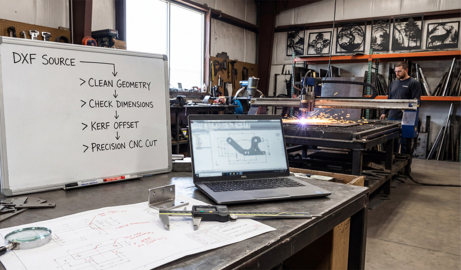
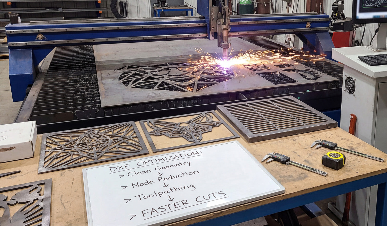
Mastering DXF File Optimization for Flawless CNC Cutting
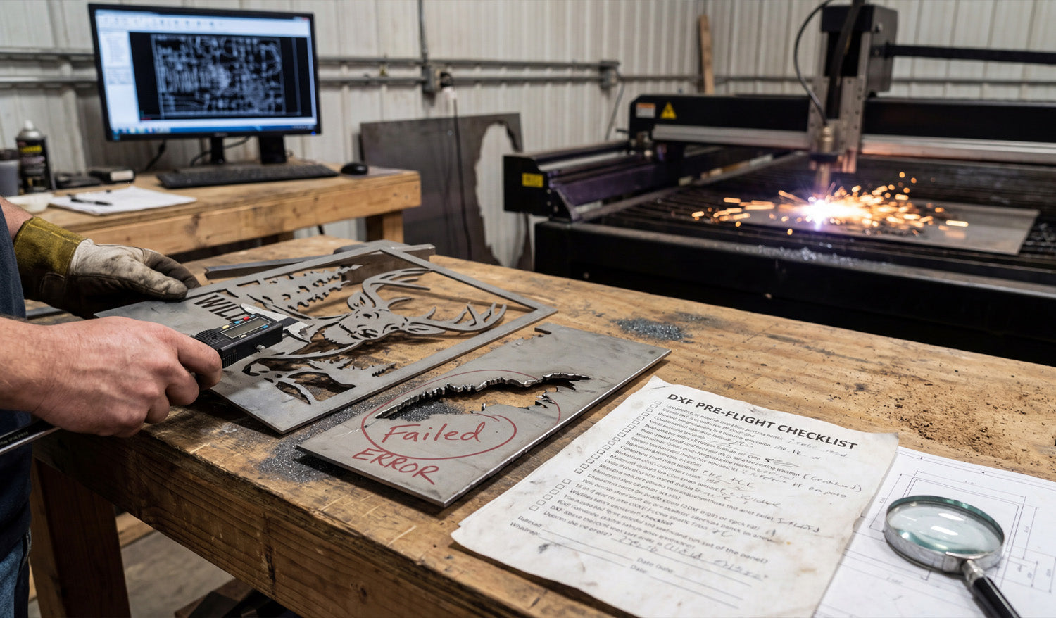
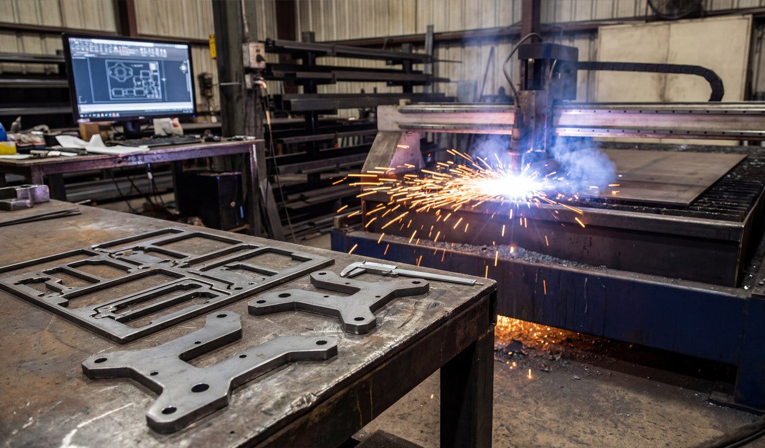
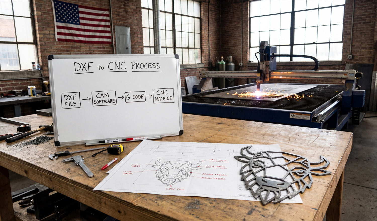
There is nothing more frustrating for a CNC operator than loading a design into the machine software, only to find the screen filled with red error warnings or seeing the cutter perform erratic, jittery movements. The difference between a smooth manufacturing process and a wasted afternoon often comes down to one critical factor: DXF File Optimization. A drawing that looks perfect to the human eye can be a disaster for a CNC machine if the underlying vector data consists of broken paths, excessive nodes, or overlapping lines. In this guide, we will explore the technical necessity of clean vector files and how using optimized designs acts as the foundation for a profitable CNC business. The Hidden Anatomy of a DXF File To understand optimization, we must first understand how your CNC machine "sees" a file. Whether you are using a plasma cutter, laser, or waterjet, the machine follows specific coordinates (G-Code) generated from your DXF file. A standard graphic design intended for printing or web use often contains thousands of tiny, unnecessary dots (nodes). When a CNC machine tries to process these thousands of nodes, the motors constantly accelerate and decelerate for every microscopic movement. This results in: Rough Edge Quality: The cut looks serrated rather than smooth. Machine Vibration: Excessive shaking that leads to mechanical wear. Slower Cut Speeds: The machine cannot reach its optimal feed rate. An optimized DXF file reduces these thousands of nodes into smooth, continuous arcs (polylines) that allow the machine to glide effortlessly through the material. Common DXF Errors That Cost You Money If you are designing your own files or downloading them from unreliable sources, watch out for these three profitability killers: 1. Open Contours (Broken Paths) For a machine to cut a shape out, the line must be a continuous loop. If there is a microscopic gap between two lines—even 0.001mm—the software cannot determine the "inside" versus the "outside" of the part. This prevents the generation of a toolpath (offset) and stops production dead in its tracks. 2. Line Intersections and Overlaps Sometimes, vectors are stacked on top of each other. The machine interprets this as an instruction to cut the same line twice. In plasma or laser cutting, this concentrates excessive heat in one spot, leading to melted edges, warped material, or damaged consumables. 3. Self-Intersecting Loops These occur when a vector line crosses over itself, creating a confusing geometry that CAM software cannot process. This typically happens when converting low-quality raster images (JPG/PNG) into vectors automatically. Why Pre-Optimized Files Are a Business Asset In the CNC business, time is your most valuable currency. Every hour spent fixing broken nodes or joining open curves in CAD software is an hour your machine is sitting idle. Successful CNC shops focus on production, not file troubleshooting. This is exactly why we created the Full Access Bundle. Our library is not just a collection of drawings; it is a database of machine-ready, optimized files. We have done the heavy lifting of node reduction and path smoothing so that you can simply "Import, Cam, and Cut." Testing Your Machine Capabilities Optimization needs can vary slightly between a high-definition laser and a standard air plasma cutter. To assist with this learning curve, we offer free DXF designs. Using these files is a risk-free way to test your machine's settings, cut speed, and kerf width compensation before committing to larger projects. By prioritizing high-quality, clean DXF files, you extend the life of your equipment, improve the finish of your products, and ensure your customers receive the professional quality they expect.

Mastering DXF Optimization: The Key to Flawless CNC Cutting
Precision manufacturing relies entirely on the quality of the digital blueprint used to guide the machine. Whether you are running a plasma cutter, a laser machine, or a waterjet, the outcome of your project is only as good as the DXF file you feed into the controller. A flawless design ensures smooth cuts, reduces material waste, and significantly lowers the wear and tear on your equipment. However, poorly optimized files can lead to jagged edges, machine stoppages, and wasted hours of troubleshooting. Understanding the technical nuances of DXF optimization is the fastest way to transition from a hobbyist struggling with errors to a professional shop producing high-value commercial products efficiently. Why DXF File Quality Matters for Your CNC Business In the world of CNC manufacturing, time is money. Every minute your machine spends cutting "air" or retracing existing lines due to a bad file is profit leaking out of your business. High-quality DXF files are clean, closed, and contain the minimum number of nodes required to define a shape. When you use professional-grade DXF designs, you aren't just buying a pattern; you are buying guaranteed efficiency. Common DXF Errors and Practical Solutions Even seasoned CNC operators encounter "bad files." Here are the most common issues that plague CNC production and how to identify them: Open Vectors (Broken Paths): For a CNC machine to cut a shape out of a material specifically (like a metal sign), the line must form a complete loop. If there is even a microscopic gap between two lines, the software cannot determine the "inside" versus the "outside" of the cut. This often results in the software failing to generate a toolpath. Solution: Always use the "Join" or "Close Curve" function in your CAD software before exporting. Overlapping Lines (Double Cutting): This occurs when two lines are stacked directly on top of each other. To the human eye, it looks like one line. To the computer, it is two specific instructions. The machine will cut the same path twice, causing excessive heat, ruined edges, and potential damage to the torch or laser head. Excessive Node Count: A simple curve should only need a few points (nodes) to define it. Poorly converted images often contain thousands of unnecessary nodes. This causes the machine to stutter or "jitter" as it tries to process thousands of tiny movements, resulting in a rough, serrated edge finish. Optimizing Designs for Different Machines Not all DXF files are universal for every machine type. A design intended for laser cutting might have incredibly intricate details that a plasma cutter cannot physically handle due to the "kerf" width (the width of material removed by the cut). Plasma Cutters: Generally require designs with less intricate detail and wider spacing between parts to prevent the metal from warping due to heat. Laser Cutters: Can handle extremely fine details and tight tolerances, allowing for more artistic and complex patterns. If you are testing new equipment or learning the ropes, we recommend trying out our free DXF designs to understand how your specific machine handles different line weights and geometries. Monetizing Your CNC Output Once you master the technical side of DXF optimization, the commercial potential is limitless. The most profitable CNC businesses don't just sell "cutting services"; they sell finished products. Custom metal art, privacy screens, personalized signage, and fire pits are high-demand items in the US market. By utilizing a comprehensive library like our Full Access Bundle, you gain instant access to thousands of market-ready designs. This eliminates the bottleneck of designing from scratch, allowing you to focus on production and sales. In the e-commerce landscape, speed of execution is key. Having a reliable source of optimized files ensures you can say "yes" to more client orders and deliver professional results every time.

How to Avoid Common Mistakes When Using DXF Files for CNC Projects
Using DXF files for CNC projects can be incredibly powerful—but small mistakes in those files can quickly turn into wasted material, broken tools, and long nights at the machine. If you learn how to avoid the most common DXF pitfalls early, your CNC work becomes cleaner, faster, and far more predictable. 1. Not Checking Units and Scale Before CAM One of the easiest ways to ruin a job is to skip the basic “size check” when importing a DXF file. Common mistake: Designing in millimeters, importing as inches (or the opposite), so parts come in 25.4× bigger or smaller. How to avoid it: Always confirm whether the DXF was drawn in mm or inches. Measure a known feature (for example, a 50 mm edge or 2" hole spacing) right after import. If size is wrong, apply a single global scale and then lock units in your CAM template. 2. Ignoring Open Contours and Tiny Gaps DXF files can look like closed shapes on screen but still have tiny breaks that confuse CAM software. Common mistake: Assuming every outline is a closed loop just because it “looks closed” at normal zoom. How to avoid it: Zoom in on corners and intersections to hunt for small gaps. Use snap-to-endpoint plus extend/trim tools to close any openings. Use “join / polyline” tools to convert many segments into one closed contour. In CAM, test by selecting “chain” or “profile” in one click—if it stops mid-way, there is still a gap. 3. Leaving Duplicate and Overlapping Geometry Overlapping lines are invisible in CAD but very obvious on the finished part: the machine cuts the same path twice. Common mistake: Copy-pasting geometry, importing multiple versions, or tracing images and forgetting to delete old outlines. How to avoid it: Run a “delete duplicates / overkill” command if your CAD supports it. Temporarily move shapes to see if another line is hiding underneath. Rebuild messy shapes with fresh, single polylines instead of patching old ones. Verify in CAM that toolpaths show one clean pass, not two lines on top of each other. 4. Using Overly Complex Curves and Traced Artwork Automatic image traces and imported logos often come with thousands of tiny segments and random points. Common mistake: Sending raw traced geometry straight to CAM, causing choppy motion and slow feed rates. How to avoid it: Simplify curves with “optimize / simplify path” tools to reduce node count. Replace rough outlines with true arcs and circles where possible. Limit ultra-fine detail to areas where it really adds value; remove noise everywhere else. Preview toolpaths—if curves look like saw teeth instead of smooth lines, clean the DXF more. 5. Mixing Cut, Engrave, and Reference Lines on One Layer When everything lives on a single layer, it is easy to accidentally cut reference geometry or miss engraving lines. Common mistake: Exporting all entities on “Layer 0” and then sorting them manually in CAM every time. How to avoid it: Organize your DXF into clear layers such as: OUTER_CUT – final outer profiles INNER_CUT – holes and internal cutouts ENGRAVE / MARK – logos, text, bend lines REFERENCE – centerlines, notes, dimensions Use colors per layer so you can visually verify everything at a glance. Create CAM templates that map these layers directly to tools and strategies. 6. Forgetting About Kerf and Tool Diameter in the DXF Stage DXF geometry describes “perfect” shapes. Your tool or beam always has thickness—if you ignore that, parts will not fit. Common mistake: Drawing all features at nominal size without considering how kerf or bit diameter changes the final dimension. How to avoid it: Know your typical kerf width or tool diameter for each process. Use CAM’s inside/outside compensation correctly for profiles. For critical fits (slots, tabs, mating holes), edit the DXF based on real test cuts and measured results. Document standard clearances (for example, +0.1 mm, +0.2 mm) and reuse them on future designs. 7. Relying on Live Fonts Instead of Vector Text Fonts look great in your design software, but many CAM tools and controllers do not understand text entities at all. Common mistake: Leaving text as editable font objects and assuming the CNC side has the same fonts installed. How to avoid it: Before exporting to DXF, convert text to outlines/curves. Choose fonts that are CNC-friendly: bold, open shapes with limited thin strokes. For cut-through text, prefer stencil-style fonts so inner islands stay attached. Re-import your DXF into CAM as a test to confirm text looks exactly as intended. 8. Leaving Random Junk and Tiny Artifacts in the File Stray points and microscopic segments may be invisible in CAD, but the machine will still try to cut them. Common mistake: Keeping small leftovers from trimming, tracing, or copying geometry. How to avoid it: Use selection filters to find and delete very short entities below a certain length. Manually inspect tight corners and busy areas where artifacts usually hide. After cleanup, review the CAM simulation: the toolpath should not show random “spikes” or micro-moves. 9. Bad Origin and Part Placement If your DXF part is floating far away from (0,0), nesting and alignment become much more painful. Common mistake: Designing around a random base point and never repositioning the part. How to avoid it: Pick a logical origin—such as the bottom-left corner or part center. Move the entire part so that key point sits at (0,0) in CAD. Delete title blocks, borders, or old geometry that lives far from the part. Save this version as your CNC-ready DXF so every import starts clean. 10. Skipping Test Cuts and Assuming the DXF Is Perfect Even a “perfect” DXF can behave differently on a real machine with real material. Common mistake: Loading a brand-new DXF and immediately cutting a full sheet or expensive stock. How to avoid it: Run a small test cut on scrap that includes tight features, text, and critical fits. Measure parts and check how holes, tabs, and slots actually fit together. If needed, tweak either the DXF or CAM offsets, then save a “proven” version for production. Keep notes with each DXF: best material, thickness, settings, and any special tricks. Quick Checklist Before Sending a DXF to the CNC Before you press “post” or “start,” ask yourself: ✔ Are units and scale confirmed with a real measurement? ✔ Are all profiles closed, with no gaps or overlaps? ✔ Have duplicates and tiny junk entities been removed? ✔ Are curves simplified enough for smooth machine motion? ✔ Are cut, engrave, and reference lines separated on proper layers? ✔ Has text been converted to outlines and checked at real size? ✔ Is the part positioned sensibly near (0,0)? ✔ Has at least one small test cut been made and measured? Conclusion Avoiding common mistakes with DXF files is really about respecting how your CNC machine “thinks.” When you feed it clean geometry in the right units, with closed loops, sensible layers, and realistic feature sizes, CAM becomes easier, cutting becomes faster, and your finished parts match the drawing the first time. A little extra attention at the DXF stage saves a lot of time, material, and stress on the shop floor.
The Most Common Problems with DXF Files for CNC Projects and How to Fix Them
The most common problems with DXF files for CNC projects usually fall into a few repeatable categories: wrong scale, broken geometry, messy curves, and unsupported entities. The good news is that once you learn to spot these issues, they are fast to fix and your CNC jobs become much more predictable. Why DXF Problems Show Up on the CNC Machine (Not on the Screen) DXF files can look perfect in a CAD or graphics program but still fail when you import them into CAM or your machine’s software. That is because: CNC software cares about closed loops, clean paths, and real units, not just how the drawing looks. Controllers do not like duplicates, gaps, or exotic entities such as splines and hatches. Small errors get amplified once you add kerf, tool diameter, and cutting direction. Let’s walk through the most common DXF problems and how to fix each one before they cost you material and time. 1. Wrong Units or Scale Symptom: Parts import at the wrong size (for example, a 100 mm plate appears as 100 inches or tiny on screen). Why it happens: The DXF was created in one unit system (mm or inches) but opened in another, or scaled during export/import. How to Fix It In CAD, confirm whether the design was drawn in millimeters or inches. In your CAM or CNC software, check the import units and match them to the original DXF units. Measure a known feature (for example, a 50 mm hole spacing). If it is wrong, apply a single uniform scale (25.4× or 1/25.4×) once and resave. Lock the correct unit setting in your templates so future DXFs come in correctly. 2. Open Contours and Tiny Gaps Symptom: CAM will not recognize a closed profile, or toolpaths stop short of corners or leave strange uncut slivers. Why it happens: Endpoints of lines and arcs do not quite touch, leaving microscopic gaps in what should be closed loops. How to Fix It Zoom in tightly on corners and intersections to look for small breaks between entities. Use extend, trim, and snap-to-endpoint tools to make endpoints coincide exactly. Run “join” or “polyline edit > join” commands to turn multiple segments into single closed polylines. After joining, run a CAM “chain” or “select profile” command to confirm the loop is now truly closed. 3. Duplicate Lines and Overlapping Geometry Symptom: The machine cuts the same path twice, causing rough edges, extra heat, and wasted time. Why it happens: Importing files from multiple sources, copying elements, or tracing images can stack lines and arcs on top of each other. How to Fix It Use CAD commands like “overkill,” “delete duplicates,” or “purge” (name depends on your software). Select suspect areas and temporarily move geometry to see if another line is hiding underneath. Simplify complex shapes by redrawing them with clean, single-pass polylines. Recheck in CAM: toolpath preview should show one clean pass, not a double trace. 4. Too Many Nodes on Curves Symptom: The machine moves in a choppy way, slows down on curves, and leaves faceted or noisy edges. Why it happens: Shapes were created by automatic tracing or imported from low-quality vectors, resulting in thousands of tiny segments. How to Fix It Use “simplify” or “fit curve” tools to reduce node count on selected polylines. Where possible, replace curves with true arcs and circles instead of many short segments. Focus cleanup on long decorative curves and logos; that is where smoother motion matters most. Preview in CAM: after cleanup, toolpaths should display as smooth lines, not tiny zigzags. 5. Splines, Hatches, and Unsupported Entities Symptom: Parts or features disappear when imported into CAM, or only part of the geometry shows up. Why it happens: Some CAM or controller software cannot handle splines, hatches, fills, or text entities; they only understand lines, arcs, and polylines. How to Fix It Convert splines to polylines or arcs using your CAD’s “convert” tools. Delete hatches, fills, shading, and gradients—they are only for visualization, not for cutting. Explode or convert text to outlines (curves) before exporting the DXF. Keep a “cut geometry only” layer and remove all non-cut entities from the export version. 6. Tiny Unwanted Geometry and Noise Symptom: CAM shows lots of little toolpaths in weird places, or the machine spends time cutting tiny specks that do not matter visually. Why it happens: Image traces and complex imports often leave behind small stray lines, dots, or slivers that you barely notice in CAD. How to Fix It Run a “select by length” filter to find extremely short segments (for example, < 0.5 mm or < 0.02"). Delete those tiny entities if they do not contribute to the design. Simplify decorative areas with more intentional shapes and fewer tiny “spikes.” Check toolpath preview to confirm those random micro moves are gone. 7. Bad Layering and Mixed Operations Symptom: Everything imports as one big mess in CAM—cut lines, engrave lines, and reference geometry all look the same. Why it happens: The DXF creator did not use layers, or exported all entities onto a single default layer. How to Fix It In CAD, organize geometry into logical layers such as: OUTER_CUT – outer profiles INNER_CUT – holes, slots, and internal shapes ENGRAVE / MARK – text, logos, bend lines REFERENCE – centerlines, construction, dimensions Use layer colors to quickly see what is what. Export only the layers you need for cutting, or map them directly to different operations in CAM. 8. Text and Fonts That Do Not Survive Export Symptom: Text disappears, changes shape, or looks different on the CNC side compared to the design. Why it happens: Text is still a “font” object in CAD, and the CNC environment either does not have that font or does not support text entities. How to Fix It Before exporting, convert text to outlines/curves in your CAD or graphics software. Check that letters are now real vector entities (lines/arcs) instead of font objects. For cut-through text, use stencil or bold fonts that keep islands attached. Re-import your own DXF into CAM as a test to confirm the text appears correctly. 9. Wrong Origin or Part Placement Symptom: The part imports far off the screen, appears outside the work area, or is difficult to align in CAM. Why it happens: The DXF’s geometry is drawn far from 0,0 or around a random base point. How to Fix It In CAD, move the part so a logical corner or center point sits at the global origin (0,0). Remove extra geometry or title blocks sitting thousands of units away from the part. Save this origin-aligned version as your production DXF. A clean origin makes nesting, mirroring, and aligning parts in CAM much faster and less error-prone. 10. DXF Version and Compatibility Issues Symptom: The file will not import at all, or imports partially, into older CAM or controller software. Why it happens: The DXF was saved in a newer or less compatible version than your CNC software expects. How to Fix It When exporting, choose an older DXF version (for example, R12, 2000) known to work well with CNC tools. Test a small sample file first to confirm compatibility. Keep an export preset just for “CNC-safe DXF” so you do not have to remember the settings every time. Quick “Pre-Flight” Checklist for DXF Files Before sending a DXF into CAM or to your machine, ask: ✔ Are the units and scale correct? ✔ Are profiles closed with no gaps or overlaps? ✔ Have you removed duplicates, hatches, and stray junk? ✔ Are curves smooth with reasonable node counts? ✔ Are layers organized into cut, engrave, and reference? ✔ Is text converted to outlines and still readable at real size? ✔ Is the part positioned sensibly near the origin? Conclusion Most DXF problems in CNC projects come from the same small set of issues: units, open contours, duplicates, messy curves, unsupported entities, and poor layer management. Once you know how to detect and fix these problems in CAD, your DXF files become reliable, your CAM work gets faster, and your CNC machines produce cleaner, more accurate parts with fewer surprises.
How to Create Detailed DXF Files for CNC Router Projects
Creating detailed DXF files for CNC router projects is all about combining clean geometry, router-friendly details, and smart layer organization so your machine can cut crisp pockets, profiles, and inlays without extra sanding or guesswork. Understand What “Detailed” Really Means for CNC Routers On a CNC router, detail is limited not just by your design skills, but by tool diameter, step-down, spindle speed, and material. A detailed DXF for routers should: Use geometry that matches real tool sizes (no impossible sharp inside corners). Include clear pocket and profile regions for 2.5D work. Stay within the minimum feature size your bits and material can handle. The goal is artwork that looks rich and layered, but still cuts reliably with the router bits you actually own. Step 1: Choose the Right Scale and Units for Your Project Before drawing any details, lock in the scale and units of your DXF file: Use millimeters or inches consistently across all your design and CAM tools. Set the overall size of the project (for example, 600×400 mm sign or 24×18" panel). Confirm at least one key dimension (height, width, or hole spacing) with measurement tools after saving as DXF. Having the scale right from the start makes later adjustments—like pocket depth or tool choice—much easier. Step 2: Plan Detail Levels Around Bit Diameter For CNC routers, bit size is your real resolution. Your DXF should respect that from the beginning. Set a minimum gap and line width that is larger than your smallest bit diameter. Use larger radii in corners where the tool must fit; avoid needle-thin slots. For very small details (fine text, micro ornaments), plan to use engraving/V-bits instead of standard end mills. If your DXF contains gaps that are smaller than your smallest bit, the router simply cannot reproduce that detail in wood or MDF. Step 3: Start from Clean, Vector-Based Artwork If you are creating decorative panels, signs, or inlays, always work from vector geometry—not low-resolution images. Design directly in CAD or vector software with line, arc, and curve tools. If you trace a bitmap, simplify the result to remove noise and excess nodes. Replace “stair-stepped” edges with smooth arcs or Bezier curves where appropriate. A detailed DXF should be visually rich but mathematically simple; that combination cuts faster and looks cleaner on a router. Step 4: Separate Profiles, Pockets, and Engraving in the DXF Routers excel at 2.5D work: different depths for pockets, outlines, and shallow engravings. Use layers in your DXF to prepare for that. PROFILE_OUTER: Outer shape of the part (through-cuts). PROFILE_INNER: Internal cutouts that go through the material. POCKET_AREA: Regions to be cleared to a certain depth. ENGRAVE / VCARVE: Text, line art, or borders meant for shallow passes. REFERENCE: Centerlines, dimensions, and alignment marks that are not cut. When you import the DXF into CAM, you can map each layer to a different tool and cutting strategy without manually sorting geometry. Step 5: Design Pockets and Relief Areas with Router Depth in Mind Detailed router projects often rely on pockets, steps, and multi-level surfaces to create visual depth. Define pocket regions with closed shapes so CAM can flood-clear them automatically. Use stepped pockets (for example, -2 mm, -4 mm, -6 mm) to build 3D-looking relief with a 2.5D process. Give vertical walls a small corner radius that matches your bit to avoid “unreachable” sharp inside corners. By controlling pocket shapes in the DXF, you decide where the router will create shadows and depth on the final piece. Step 6: Build Router-Friendly Text and Typography Text is one of the most common “detailed” elements in CNC router projects, and it needs special attention in DXF form. Use bold, open fonts for through-cut letters to avoid fragile inside islands. Convert text to curves/outlines before exporting to DXF, so there are no missing fonts later. For small text, plan on V-carving instead of full-depth profiling, and keep letter height generous for your bit size. Well-designed text in your DXF will carve clearly, stay readable after finishing, and avoid chip-out on delicate serifs. Step 7: Use Symmetry and Arrays to Multiply Detail Efficiently Detailed router panels often repeat patterns: geometric grids, floral elements, or lattice work. Your DXF can take advantage of that. Design one tile or motif, then copy it with array/offset tools instead of drawing every segment separately. Use mirroring on left/right or top/bottom patterns to keep symmetry perfect. Align repeated elements to a clear grid so your layout stays consistent and easy to adjust. This approach lets you build complex, detailed designs while still keeping the DXF manageable and edit-friendly. Step 8: Control Node Count for Smooth Router Motion Every tiny segment in your DXF becomes a move for the router. Too many nodes slow motion and can create faceted edges. Use “simplify path” tools to reduce node density on curves without losing visible detail. Replace noisy hand-traced shapes with clean geometric primitives where you can. Focus cleanup on long decorative curves, where the router will benefit the most from smooth motion. A detailed DXF should have detail where the eye sees it—not random micro-segments that only the controller notices. Step 9: Add Alignment Features Directly in the DXF For multi-part or multi-step CNC router projects, alignment is critical. Your DXF can help build that accuracy in from the start. Add registration holes or slots used with dowels or pins for double-sided machining. Include locating pockets where other pieces or hardware will seat. Use centerlines and crosshairs on a reference layer to line up prints, clamps, or fixtures. These features make detailed assemblies much easier to glue up, screw together, or align when you move the part in multiple setups. Step 10: Test-Cut Small Sections Before Running the Full Project Before committing a large panel or expensive hardwood to a complex design, test sections of your DXF. Cut a small sample area that includes fine text, pockets, and detailed curves. Check cut quality, readability of text, and how small features hold up to sanding or finishing. Adjust feature sizes, pocket depths, and clearances in your DXF based on what you see. After one or two samples, you will know exactly how your “detailed” DXF behaves on your router and material. Organize and Name DXF Files for Repeat Router Jobs Once a detailed design is proven, save it in a way that is easy to reuse and scale. Include size and material in the filename, such as floral_panel_600x400_oak.dxf. Keep source files (CAD/vector) and final DXF exports in clearly labeled folders. Store notes about best tools and settings with the project for next time. This turns a one-time detailed project into a repeatable product or template you can cut again with minimal setup. Conclusion Creating detailed DXF files for CNC router projects is less about cramming in as many lines as possible and more about designing smart, router-ready geometry. By planning around bit size, using layers for profiles and pockets, simplifying curves, and building in alignment and 2.5D structure, you can produce DXF files that let your router cut crisp, rich designs in wood, MDF, and plastics—without endless trial and error on the machine.
How to Edit DXF Files for Maximum Precision in CNC Projects
Editing DXF files for maximum precision in CNC projects is about turning “good-looking” drawings into mathematically exact geometry with correct units, clean constraints, and features that match how your tools and materials behave in the real world. Why DXF Editing Matters More Than You Think Many DXF files look fine on screen but fall apart at the machine: Holes that are slightly off-center or the wrong size. Profiles that are almost closed but contain tiny gaps. Traced curves that look smooth but are actually made of random segments. If you want tight fits, repeatable parts, and fewer surprises, you have to treat DXF editing as a precision step, not just a quick cleanup before CAM. 1. Confirm Units, Scale, and Origin First Precision starts with numbers that actually mean what you think they mean. Set units: Make sure your DXF is in millimeters or inches and your CAD/CAM software is using the same unit system. Check a known dimension: Measure a feature that should be a standard value (like a 50 mm plate or a 2" circle) to confirm scale. Define a logical origin: Move the part so a meaningful point (corner, center, or mounting hole) sits at (0,0) when possible. When units and origin are correct, every coordinate, dimension, and toolpath becomes easier to interpret and verify. 2. Turn Rough Geometry into Exact Lines and Arcs Many DXF files are born from image traces or low-quality exports. They look smooth, but the geometry underneath is messy. Replace polyline “circles” with true circles: Use fit or convert tools to turn faceted holes into real circular entities. Use arcs instead of many tiny segments: Where possible, refit curves as arcs for cleaner toolpaths and more accurate radii. Lock down key angles and lengths: Edit lines so they are exactly horizontal/vertical or exactly at 30°, 45°, etc., not 44.98°. Exact geometry makes kerf compensation and dimension checks trustworthy instead of approximate. 3. Close All Profiles and Remove Micro Gaps Open contours are one of the most common sources of CNC issues. CAM may skip them, misinterpret them, or require extra manual fixing. Use “extend” and “trim” tools to make lines meet precisely at endpoints. Zoom in aggressively: Small gaps can hide at corners and intersections, especially after scaling. Use “join” or “polyline edit” tools to combine segments into single closed loops. Every profile you send to CAM should be a clean, closed path with no overlaps or tiny breaks. 4. Add Constraints and Dimensions in CAD, Not at the Machine To achieve maximum precision, do not rely on “eyeballing” geometry or editing dimensions in CAM only. Apply geometric constraints: Make lines parallel, perpendicular, concentric, or tangent where appropriate. Use driven dimensions: Add dimensions in CAD that show critical distances and compare them against your design requirements. Adjust geometry via dimensions: For critical fits, type exact numbers instead of dragging endpoints with the mouse. Once your constrained sketch matches your intended dimensions exactly, export the DXF as your “precision truth” for CAM. 5. Size Holes, Slots, and Tabs for Real CNC Kerf DXF precision is not only math on screen—it has to account for the physical reality of your tool or beam. Compensate for kerf: If you know your laser or plasma cuts undersized holes, oversize the DXF hole diameter slightly. Design clearance into slots and tabs: For press-fit or slip-fit joints, adjust sizes by known clearance values (for example, +0.1 mm, +0.2 mm) based on real test cuts. Standardize feature sizes: Use consistent hole and slot dimensions that match your most common tools and fasteners. By editing the DXF to match how your machine actually cuts, you get accurate fit without constant manual tweaking at the CAM stage. 6. Align Features to a Common Datum Precision CNC work often depends on a clear reference, or datum, that all critical features relate to. Choose a primary datum: For example, the bottom-left corner or centerline of the part. Snap key features to that datum: Align bolt circles, pockets, and slots relative to that reference, not to random edges. Maintain symmetry: If the part should be symmetrical, edit the DXF so features mirror perfectly across the centerline. Awell-defined datum structure makes alignment, fixturing, and inspection far more consistent. 7. Clean Up Imported or Customer-Supplied DXF Files When customers send you “finished” DXF files, they often are not as finished as they think. Precision editing is your job. Check for overlapping geometry: Remove double lines and stacked entities that can cause double cuts. Normalize layers: Move important features onto your standard set of layers (profiles, holes, engrave, reference). Fix bad offsets: Correct poorly offset curves that create uneven wall thickness or inconsistent edge spacing. After cleanup, save a revised version clearly labeled as your production-ready DXF for that project. 8. Use Snaps and Grids Instead of Freehand Editing Precision and freehand mouse movements do not mix. Snap tools exist to keep your edits mathematically exact. Turn on endpoint, midpoint, center, and intersection snaps when editing. Use a grid or construction lines for aligning holes, slots, and cutouts. Avoid dragging entities without snaps unless you are intentionally making a non-critical visual change. Snaps and grids ensure that every edit lands exactly where it belongs, not a few tenths of a millimeter off. 9. Compare the Edited DXF Against a Reference Drawing For high-precision jobs with formal drawings, don’t trust memory—verify. Keep the original 2D drawing (PDF or CAD) open alongside your DXF. Check all critical dimensions: hole positions, slot widths, part size, and key offsets. Use dimension tools to confirm that your edited DXF still matches the official print. If there is a mismatch, either fix the DXF or request a clarified drawing before cutting expensive material. 10. Save and Document “Production-Grade” DXF Versions Once a DXF has been edited and proven accurate on the machine, lock it in as a trusted version. Use a clear naming scheme, for example: partname_precise_R2.dxf or partname_prod_R3.dxf. Store the DXF together with test notes: material, thickness, machine, and any special offsets used. Avoid casual edits to the production file; make changes as a new revision instead. Over time, you build a small library of “known good” precision DXF files that you can run again with confidence. Quick Precision Editing Checklist Before sending a DXF file to CAM for a critical CNC job, ask: ✔ Are units, scale, and origin correct? ✔ Are key lines and arcs exact, not almost straight or almost round? ✔ Are all profiles fully closed and free of duplicates? ✔ Are holes, slots, and tabs sized for real-world kerf and fit? ✔ Are features aligned to a clear datum and symmetry where required? ✔ Has the DXF been checked against a drawing or reference dimensions? ✔ Is this version labeled and saved as the production-grade file? Conclusion Editing DXF files for maximum precision in CNC projects is about moving from “looks right” to “is right.” By correcting units, refining geometry, closing gaps, aligning features to datums, and sizing everything for real tools and kerf, you turn DXF files into reliable blueprints that your CNC machines can follow with tight tolerances and repeatable accuracy.
Optimizing DXF Files for Faster CNC Cutting: Tips for Pros
Optimizing DXF files for faster CNC cutting is about reducing wasted motion, cleaning up geometry, and feeding your laser, plasma, or router toolpaths that cut quickly without sacrificing accuracy or edge quality. Why DXF Optimization Matters for Pro CNC Shops When you run CNC machines for a living, every second of cycle time turns into real money. Poorly prepared DXF files cause: Excessive rapid moves and pierces that slow cycles down. Choppy motion that limits feed rates and leaves rough edges. Extra setup time in CAM every time a repeat job comes back. Optimized DXF files let you cut faster at the same quality—or better—while keeping nesting, programming, and re-runs under control. 1. Start with Clean, Lightweight DXF Geometry Fast toolpaths start with clean data. Before you even open CAM, make sure your DXF is in good shape: Delete duplicates: Remove overlapping lines and arcs that cause double cuts. Close profiles: Ensure every outer and inner contour is a fully closed loop. Strip junk: Remove dimensions, construction lines, points, and tiny fragments. Join polylines: Convert short segments into continuous polylines wherever possible. The goal is a DXF that looks “boring” to CAD but beautiful to CAM—minimal entities, maximum clarity. 2. Control Node Density on Curves for Higher Feed Rates Too many nodes on a curve slow the machine down. The controller has to process every point, which kills acceleration. Use “simplify” or “optimize curve” tools to reduce node count on arcs and splines. Replace traced, stair-stepped outlines with true arcs and circles where possible. Focus on decorative areas first—logos, scrollwork, and filigree usually contain the worst offenders. Smoother geometry translates into smoother motion, allowing you to push feeds higher without jerky movement or visible facets. 3. Design with Toolpath Strategy in Mind DXF optimization is not only about shape—it is about how the machine will move through those shapes. Favor long continuous paths: Merge small adjacent segments into single profiles so the tool stays down longer. Avoid needless breaks: Don’t split contours just because it is convenient for drawing; every break becomes a stop. Eliminate “micro features”: Tiny zigzags, micro tabs, and decorative spikes add time but no value. Think like the machine: every start, stop, and direction change costs you time. Draw your DXF so the cutter can flow. 4. Use Layers to Drive Faster CAM Setup Pros cut the same types of parts over and over. Layers let you standardize your CAM workflow so you are not reprogramming from scratch. Create a consistent layer set: OUTER_CUT, INNER_CUT, ENGRAVE, MARK, REF. Put each entity on the correct layer as you design or clean the DXF. Build CAM templates that auto-map layers to tool, speed, and cut rules. When your DXF files arrive layered correctly, programming becomes a few clicks instead of a fresh setup for every job. 5. Nest for Speed, Not Just Scrap Reduction It is tempting to chase maximum material usage, but sometimes the fastest nest is not the tightest one. Align cut direction: Group parts so the machine can run long, continuous passes instead of zigzagging randomly. Leave sensible spacing: Enough room to avoid heat distortion (plasma/laser) and collision issues. Use pattern repetition: Arrange repeating parts in rows or columns that cut in a logical sequence. Balanced nesting—good yield plus smart cut paths—often beats ultra-tight nests that force slow, fragmented motion. 6. Reduce Pierces and Retracts in DXF-Driven Jobs Pierces and retracts are some of the biggest time sinks, especially for plasma and laser cutting. Combine islands where possible: Avoid lots of tiny isolated shapes that each require a separate pierce. Use slots instead of many small holes when functionally acceptable. Design for common-line cutting (shared edges) on plasma/laser to eliminate redundant passes between adjacent parts. Minimize micro cutouts: Replace clusters of small decorative holes with fewer, more substantial features. Every pierce you save shortens the cycle time and extends consumable life at the same time. 7. Simplify Text and Logos for Production Speed What looks great in a graphic design program can be a nightmare on the table. Use production-friendly fonts for cut text—bold, open shapes with minimal islands. Convert logos into clean, single-line or silhouette versions instead of ultra-detailed traces. Remove micro-details that disappear after paint or powder coat anyway. The right simplification keeps the look on-brand while cutting minutes off each part. 8. Create Machine-Specific DXF Variants Pros often run the same design on different machines. A “one-size-fits-all” DXF is rarely truly optimized. Maintain variants like _LASER, _PLASMA, _ROUTER with detail tuned to each process. Increase minimum feature sizes for plasma; preserve finer details for laser-only versions. Adjust internal radii and slot widths to match typical tool diameters on your router or mill. Machine-specific DXFs let you run faster feeds and more aggressive strategies without worrying about process limitations. 9. Bake Shop Standards into Your DXF Templates The fastest way to optimize is to stop reinventing the rules. Turn your best practices into DXF templates and design guidelines. Define minimum bridge widths, hole diameters, and text heights per machine and material. Standardize on a kerf allowance and clearance strategy for tabs and slots. Document preferred layer names and colors so everyone in the team uses the same structure. When designers follow these standards, DXFs arrive on the shop floor already optimized for speed. 10. Build a Proven “Fast-Cut” DXF Library Once a file is tuned for speed and quality, treat it like gold. Save the final, validated version under a clear name like partname_fastcut_v3.dxf. Store DXFs, CAM files, and recommended settings together in a project or library folder. Use these proven files as the base for new variants (different sizes, hole patterns, or arrays). Over time, your library of production-proven DXF files becomes a competitive advantage—new jobs program and run much faster. Quick Pro Checklist for Faster CNC Cutting with DXF Before you release a job to the floor, confirm: ✔ Geometry is clean: no duplicates, gaps, or junk entities. ✔ Curves have optimized node counts for smooth, fast motion. ✔ Layers map directly to your standard CAM templates. ✔ Nests are arranged for logical, continuous cutting—not just tight packing. ✔ Pierce count, retracts, and micro features are minimized. ✔ Text, logos, and decorative details are simplified for production. ✔ Machine-specific variants exist where necessary (laser, plasma, router). Conclusion Optimizing DXF files for faster CNC cutting is a mindset as much as a technique. When you design and clean geometry with toolpaths, pierces, nesting, and machine behavior in mind, your laser, plasma, and router tables run faster, parts look better, and every repeat job gets easier to program. For a pro shop, that combination of speed and consistency translates directly into higher throughput and better margins.
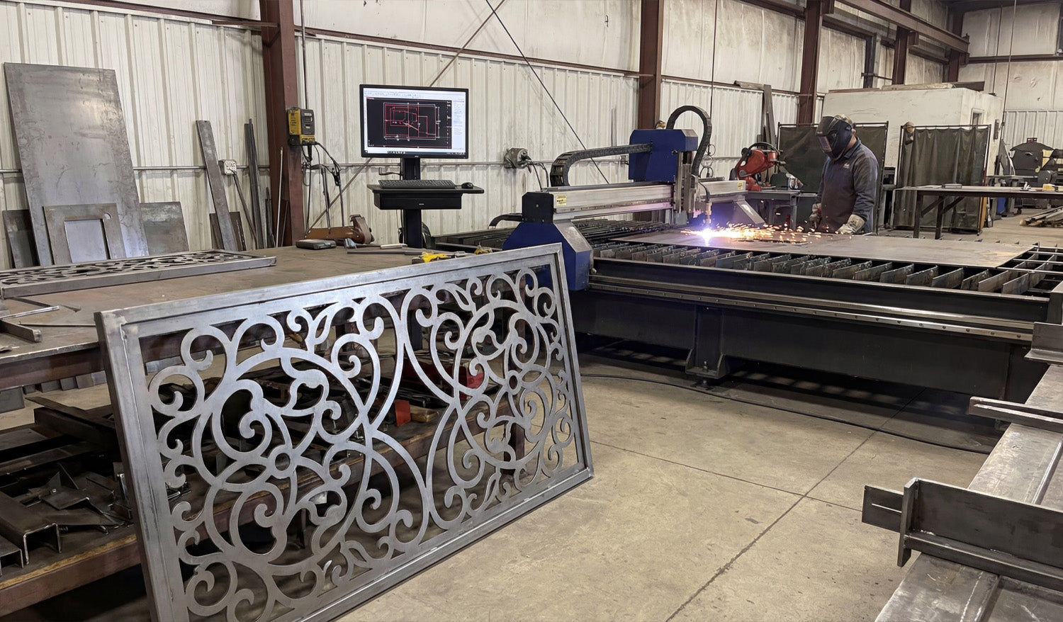
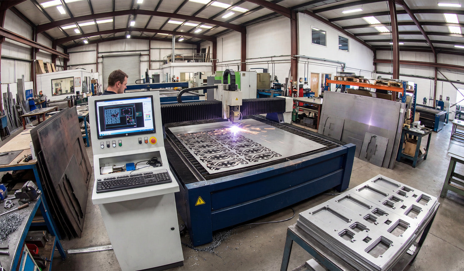
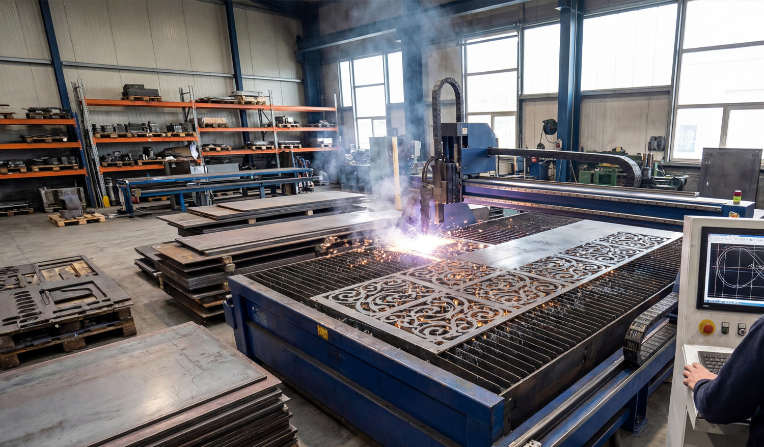
How to Create Perfectly Optimized DXF Files for CNC Plasma Cutting
Creating perfectly optimized DXF files for CNC plasma cutting is less about “pretty artwork” and more about smart geometry, correct kerf planning, and designs that match how plasma really behaves on steel, stainless, or aluminum. Why Plasma Needs Special DXF Optimization Plasma cutting is powerful but not delicate like a fine laser. It has a wider kerf, more heat, and slightly rougher edges. If your DXF file is built like it is going to a laser or a router, you will fight: Blown-out small details and thin bridges. Out-of-round holes and distorted slots. Warped parts from long, unplanned cuts. Parts falling into the table mid-cut because the skeleton is weak. Optimizing DXF files for plasma means designing shapes, holes, and text that cut cleanly at plasma scale and thickness—not just on your monitor. Step 1: Lock In Units, Material, and Thickness Before You Draw Great plasma DXF work starts before the first line is drawn. Pick your units: Decide on millimeters or inches and set your CAD/vector software accordingly. Choose material and thickness: 3 mm mild steel, 10 mm plate, 1/4" aluminum, etc. This will drive your minimum feature sizes. Note your machine’s kerf range: Different nozzles and amps produce different kerf widths. Write these three things down (units, material, thickness) in project notes. Every design decision you make in the DXF should respect them. Step 2: Design Plasma-Friendly Geometry Plasma loves bold, sturdy shapes and hates fragile, tiny details. Use that rule to guide your DXF design. Minimum web/bridge width: Keep thin connections and webs clearly larger than the kerf and strong enough to survive slag and cleanup. Simplify fine detail: Remove tiny spikes, hairline gaps, and micro cutouts that will just burn away or fuse. Round sharp internal corners: Add small radii; plasma naturally rounds corners, so design with that in mind. Use bold shapes for small parts: The smaller the part, the more robust it should be in the DXF. If a detail would be hard to cut by hand with a plasma torch, it is probably too small for CNC plasma at production speeds. Step 3: Plan for Good Hole and Slot Quality Holes and slots are where plasma shows its personality. If your DXF does not respect plasma rules, holes end up tapered, egg-shaped, or undersized. Respect minimum hole size: Avoid tiny holes that are close to your kerf width. As a simple rule of thumb, make hole diameters significantly larger than the kerf and at least a bit larger than material thickness. Use true circles in the DXF: Draw holes as real circles or arcs, not as rough polygons or traced shapes. Keep holes away from edges: Do not push holes too close to outside profiles where heat can distort them. Oversize holes slightly if needed: If real cuts come out tight, you can build that correction into the DXF for repeat jobs. The more consistent your DXF hole geometry is, the easier it is to dial in repeatable plasma settings for clean, round holes. Step 4: Clean the DXF Geometry Until It Is “Boring” A perfectly optimized plasma DXF looks boring to a CAD nerd—and that is good. Plasma loves clean, simple geometry. Delete duplicates: Remove overlapping lines and arcs that would cause double cuts and ugly edges. Close all contours: Make sure every outer profile and inner cutout is a fully closed loop. Remove junk: Delete construction lines, tiny islands, specks, and artifacts from tracing. Join polylines: Convert many small segments into continuous polylines wherever possible. Simplify curves: Use “simplify path” tools to reduce node count without changing the visible shape. The goal is geometry your CAM software can read in one pass, without guessing or patching gaps for you. Step 5: Use Layers to Separate Cut Types Even if your plasma jobs are “just cutting,” layers make your DXF safer and faster to program. Create layers such as CUT_OUTSIDE, CUT_INSIDE, MARKING, and REFERENCE. Put outer profiles (final part outlines) on CUT_OUTSIDE. Place holes, slots, and inner cutouts on CUT_INSIDE. Use MARKING for layout marks, bend lines, or weld location marks. Keep centerlines, dimensions, and notes on REFERENCE so they are never cut. With this structure, you can quickly map each layer to different plasma settings or decide to ignore layers like REFERENCE in CAM. Step 6: Think Ahead About Pierce Points and Lead-Ins Plasma cuts do not start magically. Each path begins with a pierce that creates a rougher spot. If your DXF does not leave room for that pierce, you lose precision or aesthetics. Avoid pierces on critical edges: Give CAM room to place pierces away from tight corners or visible design areas. Leave “landing zones”: In your shapes, consider where lead-ins can safely start and end without leaving marks in important areas. Use loops or small tabs if needed: Slight design tweaks can give your software a safe place to enter and exit the cut. You do not draw lead-ins inside the DXF, but you design the shapes so that good lead-ins are possible and obvious. Step 7: Design for Skeleton Strength and Part Stability On plasma tables, the “skeleton” (what is left of the sheet) matters. A perfect DXF does not cause the skeleton to collapse or eject parts prematurely. Avoid ultra-thin slivers: Long, narrow strips between parts twist and catch on the torch head. Stagger cuts: When nesting, avoid placing many long, parallel cuts side by side in the same area. Plan tabs for small parts: For tiny parts, add tabs in CAM and design shapes that can accept them without ruining the look. Keep key support areas intact: Do not cut away everything in one region; leave material to support later cuts. Designing with skeleton behavior in mind is one of the biggest differences between “art DXF” and “production plasma DXF.” Step 8: Match Detail Level to Material Thickness The same DXF should not be used blindly for 3 mm sheet and 20 mm plate. Thickness changes everything. Thin material (sheet): You can keep more detail, but watch out for heat distortion and flimsy bridges. Thick plate: Simplify internal detail, beef up text and ornaments, and avoid tiny cutouts that will trap dross. Per-thickness variants: Consider saving separate DXF versions tuned for specific thickness ranges. A design that looks perfect in 3 mm can be a nightmare in 12 mm. Your DXF library is stronger when you create versions optimized for the real plate you cut. Step 9: Export a Plasma-Friendly DXF Version Many CAM and controller packages are happiest with older, simpler DXF flavors. Export as a widely supported version such as R12 or R14 DXF when possible. Strip out unneeded items: hatches, dimensions, 3D entities, and embedded images. Verify that layers, colors, and line types came across correctly in a DXF viewer. The lighter and cleaner your exported DXF is, the fewer headaches you will have at the plasma table. Step 10: Test Cut, Measure, and Lock In the “Production” File No DXF is truly “perfectly optimized” until it has been cut and checked at least once on the real machine. Run a test cut on scrap or offcut material using your export DXF. Measure holes, slots, tab fits, and overall sizes with calipers. Note which features are too fragile, too tight, or not worth the cut time. Tweak the DXF as needed (hole diameters, bridge widths, simplified detail) and save a new version marked as production ready. From that point on, your plasma DXF is not just “nice artwork”—it is a proven, optimized pattern you can run again and again with confidence. Quick Plasma DXF Checklist Before you send a DXF to your CNC plasma cutter, ask: ✔ Units, material, and thickness are clearly defined. ✔ All profiles are closed, and there are no duplicate or stray entities. ✔ Detail level matches plasma kerf and material thickness. ✔ Holes and slots are drawn as true circles/slots and sized for real-world cutting. ✔ Layers cleanly separate outside cuts, inside cuts, marking, and reference geometry. ✔ Geometry allows safe pierce locations and lead-ins away from critical edges. ✔ The nested layout preserves skeleton strength and small-part stability. ✔ At least one test cut has been made, measured, and used to refine the final DXF. Conclusion Creating perfectly optimized DXF files for CNC plasma cutting is about designing for the reality of plasma—not for the perfection of the CAD screen. When you control geometry, hole quality, detail level, skeleton behavior, and DXF export, your plasma table stops being a guessing game and becomes a predictable, efficient production tool that turns bold vector designs into strong, clean metal parts.
How to Use DXF Files for Efficient CNC Cutting of Complex Shapes
Using DXF files for efficient CNC cutting of complex shapes is all about combining clean vector design, smart nesting, and machine-aware toolpaths so your laser, plasma, router, or mill can handle detailed parts without wasting time or material. Why DXF Files Are Ideal for Complex CNC Shapes DXF (Drawing Exchange Format) files store geometry as vectors—lines, arcs, and curves—rather than pixels. This makes them perfect for complex CNC cutting because: Curves and contours remain smooth at any size. Toolpaths can follow precise edges instead of “guessing” from a bitmap. Layers and colors can represent different operations (cut, engrave, score). Almost every CAD, CAM, and CNC controller can import DXF files. When your DXF files are prepared correctly, even very intricate patterns can be cut reliably and repeatedly across different machines and materials. Step 1: Design Complex Shapes with CNC in Mind Efficient cutting begins at the design stage. If you know a shape will be used for CNC cutting, design it with real-world constraints from the start. Define the purpose: Is it decorative art, structural, a sign, or a functional part in an assembly? Choose the machine: Laser, plasma, router, or mill—each has different minimum feature sizes and kerf. Pick the material: Steel, aluminum, wood, acrylic, MDF, etc., all respond differently to complex cuts. By setting these parameters early, you can avoid over-detailing areas that your machine or material cannot handle efficiently. Step 2: Keep Geometry Clean and Connected Complex shapes often involve many curves, cutouts, and internal details. Clean geometry is critical for efficiency. Close all contours: Ensure every outer profile and inner cutout is a closed loop—no tiny gaps. Remove duplicates: Delete overlapping lines and arcs that can cause double cuts. Eliminate stray elements: Clean out tiny fragments, construction lines, and unused blocks. Join related segments: Convert small segments into continuous polylines wherever possible. Clean DXF geometry reduces toolpath calculation time and prevents weird behavior on the CNC machine, especially around complex details. Step 3: Optimize Node Count on Curves and Contours Complex shapes tend to accumulate a lot of nodes (control points), especially if they are traced from images. Too many nodes slow down CAM and create choppy motion. Use your CAD or vector software’s simplify or optimize curve tools. Set simplification tolerances so the visual shape stays accurate but uses fewer points. Convert “stair-stepped” outlines from tracing into smoother arcs and splines. Focus on dense areas: decorative borders, filigree, and fine patterns. Optimizing node count helps your CNC machine follow complex paths smoothly and efficiently without changing the overall look. Step 4: Use Layers to Separate Complex Operations Complex DXF designs often combine different operations: through cuts, engraving, scoring, and reference geometry. Layers keep this under control. Create layers for CUT_OUTSIDE, CUT_INSIDE, ENGRAVE, SCORE, and REF. Place each element of the complex shape on the correct layer as you design. Assign distinct colors per layer if your CAM or controller maps colors to settings. Put dimensions and construction marks on a reference layer that will never be cut. Layered DXF files let you quickly assign power, speed, and depth settings to different parts of a complex design in just a few clicks. Step 5: Match Detail Level to Machine and Material Not every detail that looks great on-screen will cut cleanly or efficiently on your machine. For complex shapes, it is vital to align detail with reality. Laser: Can handle very fine detail, but avoid micro features that are smaller than the kerf or cause weak bridges. Plasma: Needs stronger, thicker details. Remove tiny islands and thin webs that will warp or blow out. Router: Limited by tool diameter; internal corners need radii or dogbones to be cut accurately. Mill: Complex contours may require multiple tools and passes; avoid impossible-to-reach recesses in 2D contour work. For efficient cutting, simplify any detail that your process cannot reliably reproduce or that dramatically slows the job without adding real value. Step 6: Plan Kerf, Bridges, and Minimum Features Complex shapes look impressive, but they must survive cutting and handling. Design your DXF with kerf and minimum feature sizes in mind. Know your kerf width for each process and material. Ensure bridges and thin webs are wider than the kerf and strong enough after cutting. Set minimum feature sizes (gap width, hole diameter, text thickness) for each machine type. Adjust critical fit features (tabs, slots, joints) for expected kerf compensation. Kerf-aware DXF designs let your complex shapes stay strong and functional instead of falling apart at the table. Step 7: Nest Complex Shapes for Efficient Material Use When cutting multiple complex shapes from sheet material, nesting is key to efficiency. Arrange shapes to maximize material usage and minimize scrap. Rotate and mirror parts where allowed to fit them more tightly together. Maintain safe spacing between complex contours to avoid heat buildup or collisions. Group similar shapes or mirrored pairs to simplify cutting order. A well-nested DXF layout for complex shapes can significantly reduce material cost and cutting time, especially on larger jobs. Step 8: Assign Smart Lead-Ins, Lead-Outs, and Cut Order Complex shapes often have many internal cutouts, spikes, and tight curves. Toolpath strategy matters as much as the geometry. Use lead-ins and lead-outs away from critical edges to avoid visible marks. Cut internal features first (holes, slots, inner details), then outer profiles last. For thin materials or small complex parts, consider tabs to keep parts from tipping or moving. Optimize cut order to minimize rapid moves and reduce the chance of heat distortion. Good toolpath planning turns a complex DXF drawing into a smooth, efficient CNC job instead of a chaotic cut sequence. Step 9: Simulate Before Cutting Complex DXF Jobs Simulation is especially important when shapes are intricate and toolpaths are dense. Simulate the full cut path in your CAM software. Watch for unexpected jumps, collisions, or strange tool behavior. Check that inside/outside compensation is correct for all contours. Review estimated cut time and see if any areas are over-detailed for the result you need. A few minutes of simulation can save sheets of material and hours of troubleshooting on complex CNC jobs. Step 10: Test on Scrap and Refine the DXF Even with a great DXF and well-planned toolpaths, complex shapes almost always benefit from one test run. Cut a small section or downsized version of the design on scrap material. Check edge quality, sharpness of detail, and strength of thin areas. Adjust power, speed, and kerf compensation as needed. Refine the DXF by thickening weak features or simplifying overly dense detail. Use what you learn from test cuts to improve both the design and the process. Save updated versions of your DXF with clear version numbers. Quick Checklist for Efficient CNC Cutting of Complex DXF Shapes Before running a complex DXF job, make sure: ✔ Units and scale are correct and verified with a known dimension. ✔ Geometry is clean: no gaps, duplicates, or stray entities. ✔ Node count on curves is optimized for smooth motion. ✔ Layers clearly separate different operations (cut, engrave, score, reference). ✔ Detail level matches your machine’s kerf and minimum feature size. ✔ Nesting is efficient and respects safe spacing. ✔ Toolpaths use smart lead-ins, lead-outs, and cut order. ✔ Simulation and at least one test cut have been completed. Conclusion Using DXF files for efficient CNC cutting of complex shapes is not just about having powerful machines; it is about feeding those machines smart, clean, and well-organized designs. By cleaning geometry, optimizing curves, using layers, planning kerf and feature sizes, nesting strategically, and testing before production, you can cut even very intricate patterns with confidence. Do this consistently, and your DXF workflow will turn complex shapes into reliable, profitable CNC projects on every job.
What Makes a Perfect DXF File for CNC Cutting?
A perfect DXF file for CNC cutting is clean, accurate, and truly machine ready, so your laser, plasma, router, or mill can cut fast and produce consistent high quality parts. What Do We Mean by a “Perfect” DXF File? In CNC work, a perfect DXF file is not just a pretty drawing. It is a 2D vector file that is ready to go straight into CAM or your machine software with minimal cleanup. A perfect DXF file should: Import at the correct real world size and units. Contain only the geometry you actually need to cut or engrave. Have clean, closed profiles and no hidden problems. Be organized in layers so operations are easy to assign. Respect the limits of your CNC machine and material. 1. Correct Units and Real World Scale The first rule of a perfect DXF file is simple: it must come in at the right size. Choose one unit system (millimeters or inches) and stick to it. Set your CAD or vector software to that unit before drawing anything. Include at least one known dimension (for example, a 100 mm or 4 inch reference) so you can confirm scale after import. If the DXF loads ten times bigger or smaller than expected, it is not CNC ready yet. A perfect DXF never makes you guess about its size. 2. Clean, Closed Geometry Most cutting problems come from messy geometry. A perfect DXF file has clean, connected shapes that CAM software can understand. Closed profiles: Outer outlines and inner cutouts are fully closed loops, not almost closed with tiny gaps. No duplicate lines: There are no overlapping segments that would cause double cutting. No stray entities: Tiny leftovers, points, construction lines, and unused blocks are deleted. Polylines when possible: Related segments are joined into continuous polylines for smoother toolpaths. Clean geometry means no surprise breaks in cuts and no strange toolpath behavior on the CNC machine. 3. Optimized Node Count for Smooth Motion Too many nodes (control points) make your machine move in a stop and go pattern and increase file size. A perfect DXF has just enough detail, but not more. Use simplify or optimize curve tools to reduce the number of points on curves. Replace jagged lines from auto tracing with smoother arcs or splines. Focus on heavily detailed zones like borders, logos, and patterns. Optimized curves keep motion smooth and help your CNC cut faster and cleaner without changing the look of the design. 4. Logical Layer and Color Organization Layers are how you tell your CAM or controller software what each line should do. A perfect DXF is always layer aware. Create layers for outside cuts, inside cuts, engraving, scoring, holes, and reference. Use clear layer names such as CUT_OUTSIDE, CUT_INSIDE, ENGRAVE, SCORE, HOLES, REF. Assign distinct colors to each layer if your laser or CAM can map settings by color. Keep dimensions and construction geometry on a reference layer that will never be cut. With a properly layered DXF, assigning power, speed, depth, and cut order in CAM takes minutes instead of a painful selection process. 5. Designed for the Specific CNC Process A perfect DXF file is not “one size fits all.” It respects the machine that will actually cut it. For Laser Cutting Fine detail is allowed, but bridges and thin elements are not so small that they burn away. Text is large enough to remain readable at the final size. Engrave and cut paths are separated by layer or color. For Plasma Cutting Small holes and micro detail that plasma cannot hold are removed or enlarged. Bridges in artwork and letters are thicker to stay strong in metal. Sharp inner corners are softened or radius added where plasma kerf would round them anyway. For CNC Routers and Mills Inside corners include dogbone or T-bone relief where needed for square fits. Slots and pockets are designed for real tool diameters and depths. Tool access is considered so there are no impossible to reach features. Machine aware design is a core part of what makes a DXF file truly perfect for CNC cutting. 6. Kerf and Tolerance Friendly Geometry Kerf is the width of material removed by the cut. A perfect DXF does not ignore it. Critical slots, tabs, and joints are drawn with the expected kerf compensation in mind. Standard hole sizes are used so you can apply consistent rules in CAM. Clearance is included for press fits, sliding fits, and glue joints where needed. Bridges and thin webs are sized so they remain strong after kerf is removed. When kerf and tolerance are considered in the design, parts fit better and require less rework after cutting. 7. Text and Logos Prepared for CNC Text and logos look simple but often cause the worst CNC issues when not prepared correctly. A perfect DXF handles them with care. All text is converted to outlines so it does not depend on system fonts. For cut out text, stencil bridges are added to keep inner islands of letters in place. Stroke widths and letter heights are big enough for the machine and material. Logos are cleaned so they do not contain micro shapes that will not cut well. Properly prepared text and logos engrave cleanly or cut out nicely without falling apart. 8. No Unnecessary Extras in the DXF File A perfect DXF is focused. It does not carry extra data that slows down your workflow. No embedded bitmaps or background images in the final cut file. No hatches, fills, or 3D entities when you only need 2D paths. No unused layers, blocks, or anonymous objects. Simple, widely compatible DXF version (often R12 or R14) when possible. Keeping the DXF lean makes it faster to load in CAM and reduces compatibility issues with different machines. 9. Consistent Naming and Documentation A perfect DXF file is not only technically clean, it is also easy to recognize and reuse. File names include part name, size, material, and version where helpful. Variants for different machines or thicknesses are clearly labeled. Optional notes or a readme describe recommended material and cutting process. This kind of organization turns a single DXF into a reliable asset that you and your team can trust in the future. 10. Tested on the Machine and Refined Finally, a DXF file only becomes “perfect” after it is tested and improved at least once. Run test cuts on scrap material before full production. Check fit, edge quality, and strength of key areas. Tweak slot sizes, bridge widths, and small features based on real results. Save the improved design as a new version so you know which one works best. Real world feedback is what turns a good DXF design into a perfect, production ready one. Quick Checklist: Is Your DXF File “Perfect” Yet? Before sending a job to your CNC machine, check: ✔ Units and scale are correct and verified with a known dimension. ✔ All profiles are closed and there are no duplicate or stray lines. ✔ Node count on curves is reasonable and motion will be smooth. ✔ Layers clearly separate cuts, engraves, scores, and reference geometry. ✔ Detail level matches the limits of your machine and material. ✔ Kerf and tolerances have been considered for joints and critical fits. ✔ Text and logos are converted to outlines and CNC friendly. ✔ The file has been test cut and refined at least once. Conclusion A perfect DXF file for CNC cutting is not magic. It is the result of clean geometry, smart layering, machine aware design choices, and real world testing. When you learn to build DXF files this way, your laser, plasma, router, or mill will run smoother, your parts will fit better, and your overall CNC workflow will feel more professional and predictable on every project.
How to Handle Large DXF Files for CNC Cutting: Tips and Tricks
Handling large DXF files for CNC cutting is all about keeping performance under control—optimizing geometry, splitting smartly when needed, and setting up your software and hardware so big jobs run smoothly instead of crashing or freezing. Why Large DXF Files Are a Challenge in CNC Cutting Big DXF files usually mean one of three things: huge physical size, extreme detail, or a lot of different parts packed into one drawing. All of these can stress your CAD, CAM, and CNC controller. Slow performance: Viewers and CAM software can lag or freeze when panning and zooming. Long toolpath generation: CAM needs more time and memory to calculate toolpaths. Controller limits: Some machines cannot handle very large G-code files smoothly. Higher risk of errors: Corrupted saves, incomplete cuts, or lost steps mid-job. The good news: with the right workflow, you can make large DXF files much more manageable. Tip 1: Start by Cleaning the Geometry Even before you worry about file size, make sure the geometry in your large DXF is clean and reliable. Remove duplicates: Delete overlapping lines and curves to avoid double cuts. Close open contours: Ensure outer profiles and internal cutouts form closed loops. Delete stray entities: Get rid of tiny line fragments, points, and unused blocks. Unify polylines: Convert many small segments into longer polylines wherever possible. Clean geometry reduces toolpath complexity and helps CAM software handle the file more efficiently. Tip 2: Reduce Node Count on Very Detailed Artwork One of the biggest causes of “heavy” DXF files is excessive node count—especially from auto-traced images or intricate art. Use simplify curve or optimize functions in your CAD/vector software. Set a reasonable tolerance so curves stay visually accurate but use fewer points. Focus on high-density areas: decorative borders, textures, or traced logos. Replace jagged polylines with smoother arcs and splines where appropriate. Fewer nodes mean lighter DXF files, faster toolpaths, and smoother motion on the CNC machine. Tip 3: Break Huge Designs into Logical Sections Instead of trying to run one giant DXF for everything, split the design into smaller, logical pieces. By physical area: Divide large wall art or panels into tiles that fit your machine bed. By part type: Separate brackets, gussets, signs, and decorative pieces into different files. By operation: Use one DXF for cutting and another for engraving if complexity is high. This approach keeps individual files lighter and easier for your software and controller to handle. Tip 4: Use Layers to Organize Complex DXF Files Layers are essential when working with large, multi-part DXF drawings. Create layers for CUT_OUTSIDE, CUT_INSIDE, ENGRAVE, SCORE, and REFERENCE. Group similar parts or repeated components into named layers. Temporarily hide layers you are not working on to improve performance. Export layer-based subsets as smaller DXFs when you only need part of the design. Well-structured layers turn one huge DXF into a set of controllable chunks that are easier to process. Tip 5: Match DXF Detail Level to Your CNC Process Not all detail is useful in real cutting. What looks beautiful on-screen may be impossible or unnecessary on the machine. For laser cutting, you can keep fairly fine detail but still avoid micro cuts smaller than your kerf. For plasma cutting, simplify tiny shapes and thin bridges that will not hold up in metal. For routers and mills, respect tool diameter—remove features your bit cannot physically reach. Reducing detail that the machine cannot realistically reproduce shrinks file size and improves cut quality. Tip 6: Use Tiling for Oversized Panels If your DXF describes a large panel or mural that exceeds your machine’s cutting area, use tiling instead of forcing one massive file. Divide the design into tiles that fit safely inside your working envelope. Add small registration marks on each tile for accurate alignment during assembly. Export each tile as its own DXF or job file for easier toolpath generation. Tiling lets you cut very large installations in manageable sections without overloading your software or controller. Tip 7: Choose the Right DXF Version Some CAM and controller software works better with older, simpler DXF versions. Try exporting in R12/R14 DXF format, which is widely supported and less “heavy.” Avoid unnecessary entities (hatches, embedded images, 3D data) when you only need 2D paths. If your software allows, strip non-essential data on export to keep files lean. Using a compatible, minimal DXF version can dramatically reduce load times for large designs. Tip 8: Upgrade Hardware Where It Matters Large DXF files demand more from your computer. Sometimes software is not the bottleneck—hardware is. More RAM: Helps CAD and CAM handle big designs and long toolpaths. Fast SSD storage: Speeds up file loading, saving, and swapping large projects. Decent CPU: CAM calculations and simulations run faster with a stronger processor. If you regularly work with huge files, a modest hardware upgrade can pay off in reduced wait times and fewer crashes. Tip 9: Manage Toolpaths Smartly in CAM When generating toolpaths from large DXF files, be intentional about how you structure the job. Generate separate toolpaths for different areas or part groups instead of one mega-path. Use cut order controls to minimize rapid moves and reduce time. Consider breaking the job into multiple G-code files or job files if your controller has size limits. Simulate your paths to catch inefficient zig-zags and unnecessary passes. Well-organized toolpaths keep your CNC running efficiently, even when the source DXF is large. Tip 10: Compress and Archive Large DXF Projects Properly When you are done designing and cutting, store large DXF projects in a way that is safe and easy to retrieve. Use ZIP archives to compress related DXF, CAM, and preview files into one package. Include readme or notes with material, thickness, and machine settings that worked well. Organize archives by project, category, or customer so you can find them quickly later. Good archiving keeps your large, complex jobs from becoming a mess of random files that no one wants to touch again. Quick Checklist for Handling Large DXF Files Before sending a big DXF job to your CNC machine, run through this checklist: ✔ Geometry is clean (no duplicates, no gaps, no stray junk). ✔ Curves are simplified with a reasonable node count. ✔ Layers are organized into cut/engrave/score/reference. ✔ File is split or tiled if it exceeds machine limits. ✔ DXF version is compatible and does not include unnecessary entities. ✔ CAM toolpaths are grouped logically and have been simulated. ✔ A test cut has verified that detail and fits are correct. Conclusion Large DXF files do not have to be a headache for CNC cutting. By cleaning geometry, reducing node count, organizing layers, splitting oversized designs into tiles, and generating smart toolpaths, you can handle big, complex projects with confidence. Combine these tips with solid hardware and a consistent file management strategy, and your CNC laser, plasma, router, or mill will be ready to tackle large DXF jobs smoothly and reliably.
How to Convert DXF Files into CNC-Ready Files for Different Machines
Converting DXF files into CNC-ready files is all about taking clean 2D geometry and turning it into the right toolpaths and machine code for your laser, plasma, router, or milling machine. DXF vs CNC-Ready Files: What’s the Difference? A DXF (Drawing Exchange Format) file is a 2D vector drawing: lines, arcs, and curves. It describes the shape of your part or artwork, but it does not tell a CNC machine how fast to move, how deep to cut, or what order to follow. CNC-ready files, on the other hand, are machine instructions. They are usually: G-code files (for routers, mills, some lasers and plasmas) with extensions like .nc, .tap, or .gcode. Controller-specific job files for branded laser and plasma systems. The goal is simple: start with a clean DXF, process it in CAM or controller software, and export the correct CNC-ready file for your specific machine. Step 1: Clean and Prepare Your DXF File Before you convert anything, make sure your DXF file is in good shape. A clean DXF makes every later step easier. Check units and scale: Confirm whether the design is in millimeters or inches and verify a key dimension. Close all profiles: Outer shapes and inner cutouts should be closed loops with no small gaps. Remove duplicate lines: Delete overlapping or stacked paths so the machine does not cut the same line twice. Simplify curves: Reduce unnecessary nodes on curves for smoother motion. Use layers: Separate cut, engrave, score, pockets, and reference geometry onto different layers if possible. Step 2: Choose the Right CAM or Controller Software DXF files are neutral. To turn them into CNC-ready files, you need CAM (Computer-Aided Manufacturing) or machine control software that understands both DXF and your machine. Laser cutters: Often use built-in controller software that imports DXF and lets you set power and speed per layer/color. Plasma tables: Use CAM software to create lead-ins, pierces, and kerf-compensated toolpaths from DXF geometry. CNC routers: Use CAD/CAM packages that can turn DXF profiles into 2D/2.5D toolpaths (profile, pocket, drill). CNC mills: Use CAM systems that support contouring, pockets, drilling cycles, and multiple coordinate systems. Pick the software that matches your machine brand, control type, and the complexity of your projects. Step 3: Import the DXF and Confirm Geometry Once you open the DXF in CAM or controller software, verify that everything came in correctly. Check the overall size and compare it to your design plan. Confirm that layers and colors are still present and readable. Look for broken contours, tiny gaps, or missing shapes that might not have imported correctly. Delete any dimensions or reference geometry that you do not want the CNC to follow. Step 4: Assign Operations to Geometry Now tell the software what each line or shape in the DXF is supposed to do. Profile cuts: Outside outlines and internal cutouts that should go all the way through. Pockets: Areas where you want to remove material to a certain depth (router and mill). Engraving / scoring: Light surface lines for logos, text, and guides. Drilling: Holes that are better done with drill cycles than with profile cuts. Many CAM packages let you select by layer or color, which makes this step much faster when your DXF is well organized. Step 5: Apply Machine-Specific Settings This is where you convert neutral DXF geometry into real-world machining instructions. Each machine type needs different settings. For CNC Laser Cutting Set power, speed, and frequency for each layer (cut, engrave, score). Choose cut order (inner shapes first, outer profiles last). Decide between vector-only (lines and curves) and raster engraving for fills. Apply kerf compensation if supported, or adjust dimensions in the DXF for critical fits. For CNC Plasma Cutting Set material type and thickness in the CAM software. Define kerf width, lead-ins, and lead-outs for each contour. Configure pierce height, cut height, and pierce delay for clean starts. Optimize cut order to reduce warping and minimize pierces. For CNC Routers Choose the right tool diameter, flute count, and material in the tool library. Set spindle speed, feed rate, and plunge rate based on material and tool. Define cut strategies: profile inside / outside, pocketing, and drilling. Add tabs to hold parts in place during cutting. Apply stepdown (depth per pass) and stepover for efficient removal. For CNC Milling Machines Set up your work coordinate system (WCS) and origin (corner, center, or feature). Assign roughing and finishing toolpaths to contours and pockets. Use correct drilling cycles (peck, tap, ream) for hole geometry. Define depths, stepdowns, feeds, and speeds with respect to tool and material. Step 6: Generate Toolpaths and Simulate Once operations and settings are in place, tell the CAM software to create toolpaths. Check that all outer edges are cut from the correct side (inside vs outside compensation). Verify that all holes and pockets are included and at the correct depth. Run a simulation to see how the tool moves and how long the job will take. Look for collisions, air cuts, or strange moves that suggest a setup problem. Simulation is your chance to catch mistakes before they damage material or tools. Step 7: Post-Process to Create CNC-Ready Files Post-processing is the final step that converts toolpaths into the exact format your machine controller expects. Choose the correct post-processor for your machine (for example, GRBL, Mach3, Fanuc, or a brand-specific post). Export the program with a clear name, such as partname_machine_material_v1.nc. Review the generated code if you are comfortable reading G-code (optional but helpful). Now you have a CNC-ready file that your machine can run, generated from your original DXF design. Step 8: Run Test Cuts and Refine For new designs or new materials, always test before full production. Run the program on scrap or offcut material first. Check fit, edge quality, and detail (especially holes, tabs, and thin features). Adjust feeds, speeds, power, or kerf compensation as needed. Update your CAM setup and re-post the CNC-ready file once you are satisfied. Save your successful DXF + CAM + post-processor combination as a template for future jobs. Quick Reference: DXF to CNC-Ready by Machine Type Machine Type From DXF You Need To CNC-Ready Output Laser Cutter Assign cut / engrave / score layers, set power & speed, choose cut order. Laser job file or G-code depending on controller. Plasma Cutter Set material, kerf, lead-ins/outs, pierce settings, and cut direction. G-code or table-specific job file. CNC Router Pick tools, feeds, speeds, pockets, profiles, tabs, and depths per pass. G-code (e.g., .nc, .tap, .gcode). CNC Mill Define WCS, contours, pockets, drilling cycles, rough/finish paths. Controller-specific G-code program. Conclusion Converting DXF files into CNC-ready files is a repeatable process: clean the geometry, import into CAM or controller software, assign operations, apply machine-specific settings, generate toolpaths, and post-process to the correct code format. When you follow these steps—and tune them for each type of machine—you can take any good DXF design and turn it into reliable, production-ready CNC programs for lasers, plasmas, routers, and mills with confidence.

