The most common problems with DXF files for CNC projects usually fall into a few repeatable categories: wrong scale, broken geometry, messy curves, and unsupported entities. The good news is that once you learn to spot these issues, they are fast to fix and your CNC jobs become much more predictable.
Why DXF Problems Show Up on the CNC Machine (Not on the Screen)
DXF files can look perfect in a CAD or graphics program but still fail when you import them into CAM or your machine’s software. That is because:
- CNC software cares about closed loops, clean paths, and real units, not just how the drawing looks.
- Controllers do not like duplicates, gaps, or exotic entities such as splines and hatches.
- Small errors get amplified once you add kerf, tool diameter, and cutting direction.
Let’s walk through the most common DXF problems and how to fix each one before they cost you material and time.
1. Wrong Units or Scale
Symptom: Parts import at the wrong size (for example, a 100 mm plate appears as 100 inches or tiny on screen).
Why it happens: The DXF was created in one unit system (mm or inches) but opened in another, or scaled during export/import.
How to Fix It
- In CAD, confirm whether the design was drawn in millimeters or inches.
- In your CAM or CNC software, check the import units and match them to the original DXF units.
- Measure a known feature (for example, a 50 mm hole spacing). If it is wrong, apply a single uniform scale (25.4× or 1/25.4×) once and resave.
- Lock the correct unit setting in your templates so future DXFs come in correctly.
2. Open Contours and Tiny Gaps
Symptom: CAM will not recognize a closed profile, or toolpaths stop short of corners or leave strange uncut slivers.
Why it happens: Endpoints of lines and arcs do not quite touch, leaving microscopic gaps in what should be closed loops.
How to Fix It
- Zoom in tightly on corners and intersections to look for small breaks between entities.
- Use extend, trim, and snap-to-endpoint tools to make endpoints coincide exactly.
- Run “join” or “polyline edit > join” commands to turn multiple segments into single closed polylines.
- After joining, run a CAM “chain” or “select profile” command to confirm the loop is now truly closed.
3. Duplicate Lines and Overlapping Geometry
Symptom: The machine cuts the same path twice, causing rough edges, extra heat, and wasted time.
Why it happens: Importing files from multiple sources, copying elements, or tracing images can stack lines and arcs on top of each other.
How to Fix It
- Use CAD commands like “overkill,” “delete duplicates,” or “purge” (name depends on your software).
- Select suspect areas and temporarily move geometry to see if another line is hiding underneath.
- Simplify complex shapes by redrawing them with clean, single-pass polylines.
- Recheck in CAM: toolpath preview should show one clean pass, not a double trace.
4. Too Many Nodes on Curves
Symptom: The machine moves in a choppy way, slows down on curves, and leaves faceted or noisy edges.
Why it happens: Shapes were created by automatic tracing or imported from low-quality vectors, resulting in thousands of tiny segments.
How to Fix It
- Use “simplify” or “fit curve” tools to reduce node count on selected polylines.
- Where possible, replace curves with true arcs and circles instead of many short segments.
- Focus cleanup on long decorative curves and logos; that is where smoother motion matters most.
- Preview in CAM: after cleanup, toolpaths should display as smooth lines, not tiny zigzags.
5. Splines, Hatches, and Unsupported Entities
Symptom: Parts or features disappear when imported into CAM, or only part of the geometry shows up.
Why it happens: Some CAM or controller software cannot handle splines, hatches, fills, or text entities; they only understand lines, arcs, and polylines.
How to Fix It
- Convert splines to polylines or arcs using your CAD’s “convert” tools.
- Delete hatches, fills, shading, and gradients—they are only for visualization, not for cutting.
- Explode or convert text to outlines (curves) before exporting the DXF.
- Keep a “cut geometry only” layer and remove all non-cut entities from the export version.
6. Tiny Unwanted Geometry and Noise
Symptom: CAM shows lots of little toolpaths in weird places, or the machine spends time cutting tiny specks that do not matter visually.
Why it happens: Image traces and complex imports often leave behind small stray lines, dots, or slivers that you barely notice in CAD.
How to Fix It
- Run a “select by length” filter to find extremely short segments (for example, < 0.5 mm or < 0.02").
- Delete those tiny entities if they do not contribute to the design.
- Simplify decorative areas with more intentional shapes and fewer tiny “spikes.”
- Check toolpath preview to confirm those random micro moves are gone.
7. Bad Layering and Mixed Operations
Symptom: Everything imports as one big mess in CAM—cut lines, engrave lines, and reference geometry all look the same.
Why it happens: The DXF creator did not use layers, or exported all entities onto a single default layer.
How to Fix It
- In CAD, organize geometry into logical layers such as:
- OUTER_CUT – outer profiles
- INNER_CUT – holes, slots, and internal shapes
- ENGRAVE / MARK – text, logos, bend lines
- REFERENCE – centerlines, construction, dimensions
- Use layer colors to quickly see what is what.
- Export only the layers you need for cutting, or map them directly to different operations in CAM.
8. Text and Fonts That Do Not Survive Export
Symptom: Text disappears, changes shape, or looks different on the CNC side compared to the design.
Why it happens: Text is still a “font” object in CAD, and the CNC environment either does not have that font or does not support text entities.
How to Fix It
- Before exporting, convert text to outlines/curves in your CAD or graphics software.
- Check that letters are now real vector entities (lines/arcs) instead of font objects.
- For cut-through text, use stencil or bold fonts that keep islands attached.
- Re-import your own DXF into CAM as a test to confirm the text appears correctly.
9. Wrong Origin or Part Placement
Symptom: The part imports far off the screen, appears outside the work area, or is difficult to align in CAM.
Why it happens: The DXF’s geometry is drawn far from 0,0 or around a random base point.
How to Fix It
- In CAD, move the part so a logical corner or center point sits at the global origin (0,0).
- Remove extra geometry or title blocks sitting thousands of units away from the part.
- Save this origin-aligned version as your production DXF.
A clean origin makes nesting, mirroring, and aligning parts in CAM much faster and less error-prone.
10. DXF Version and Compatibility Issues
Symptom: The file will not import at all, or imports partially, into older CAM or controller software.
Why it happens: The DXF was saved in a newer or less compatible version than your CNC software expects.
How to Fix It
- When exporting, choose an older DXF version (for example, R12, 2000) known to work well with CNC tools.
- Test a small sample file first to confirm compatibility.
- Keep an export preset just for “CNC-safe DXF” so you do not have to remember the settings every time.
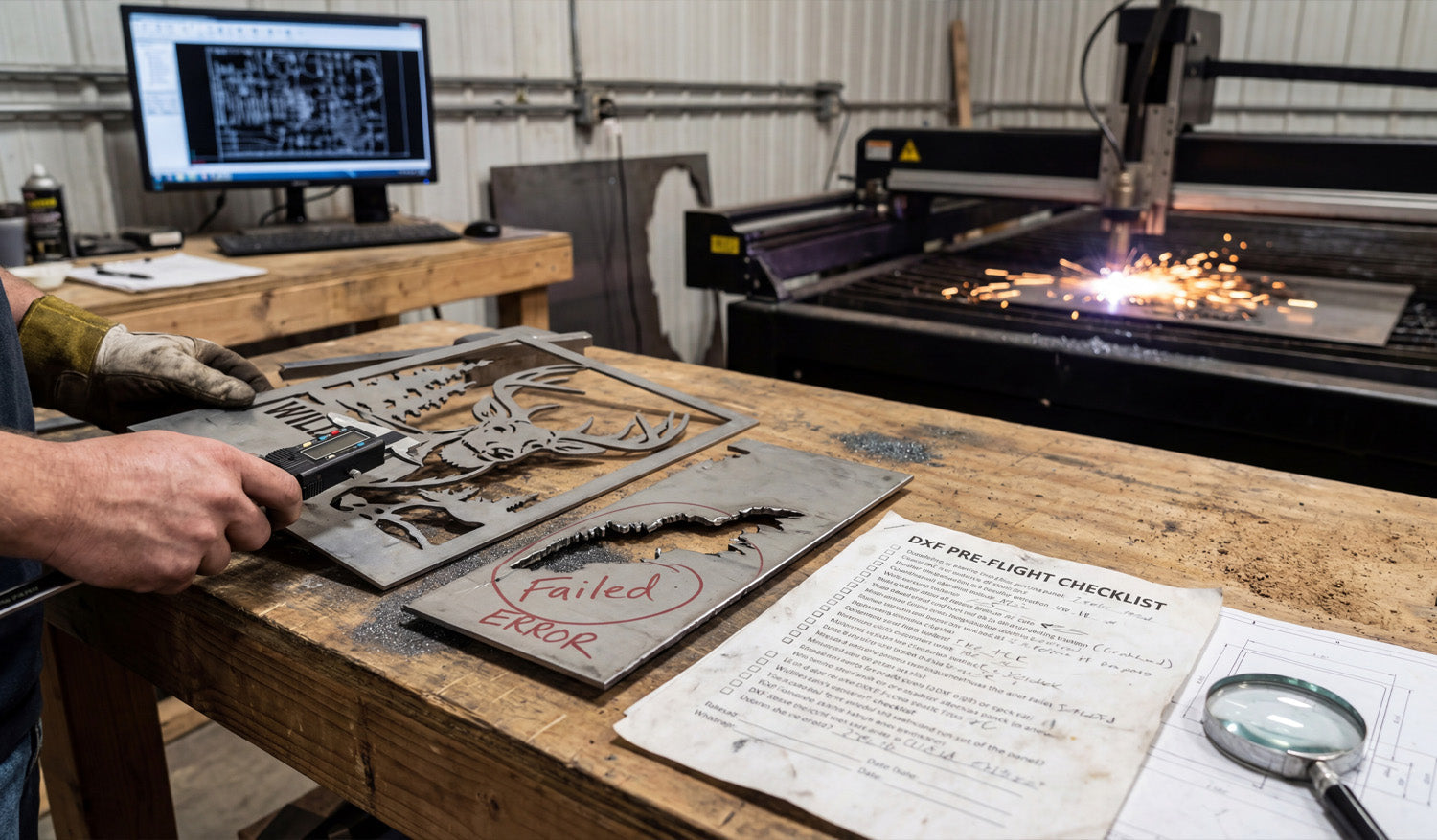
Quick “Pre-Flight” Checklist for DXF Files
Before sending a DXF into CAM or to your machine, ask:
- ✔ Are the units and scale correct?
- ✔ Are profiles closed with no gaps or overlaps?
- ✔ Have you removed duplicates, hatches, and stray junk?
- ✔ Are curves smooth with reasonable node counts?
- ✔ Are layers organized into cut, engrave, and reference?
- ✔ Is text converted to outlines and still readable at real size?
- ✔ Is the part positioned sensibly near the origin?
Conclusion
Most DXF problems in CNC projects come from the same small set of issues: units, open contours, duplicates, messy curves, unsupported entities, and poor layer management. Once you know how to detect and fix these problems in CAD, your DXF files become reliable, your CAM work gets faster, and your CNC machines produce cleaner, more accurate parts with fewer surprises.