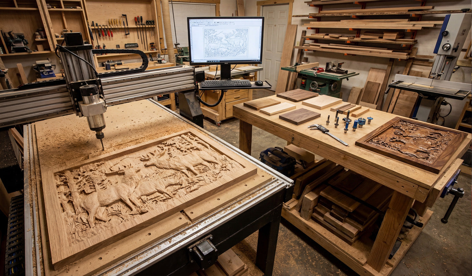
Creating detailed DXF files for CNC router projects is all about combining clean geometry, router-friendly details, and smart layer organization so your machine can cut crisp pockets, profiles, and inlays without extra sanding or guesswork.
Understand What “Detailed” Really Means for CNC Routers
On a CNC router, detail is limited not just by your design skills, but by tool diameter, step-down, spindle speed, and material. A detailed DXF for routers should:
- Use geometry that matches real tool sizes (no impossible sharp inside corners).
- Include clear pocket and profile regions for 2.5D work.
- Stay within the minimum feature size your bits and material can handle.
The goal is artwork that looks rich and layered, but still cuts reliably with the router bits you actually own.
Step 1: Choose the Right Scale and Units for Your Project
Before drawing any details, lock in the scale and units of your DXF file:
- Use millimeters or inches consistently across all your design and CAM tools.
- Set the overall size of the project (for example, 600×400 mm sign or 24×18" panel).
- Confirm at least one key dimension (height, width, or hole spacing) with measurement tools after saving as DXF.
Having the scale right from the start makes later adjustments—like pocket depth or tool choice—much easier.
Step 2: Plan Detail Levels Around Bit Diameter
For CNC routers, bit size is your real resolution. Your DXF should respect that from the beginning.
- Set a minimum gap and line width that is larger than your smallest bit diameter.
- Use larger radii in corners where the tool must fit; avoid needle-thin slots.
- For very small details (fine text, micro ornaments), plan to use engraving/V-bits instead of standard end mills.
If your DXF contains gaps that are smaller than your smallest bit, the router simply cannot reproduce that detail in wood or MDF.
Step 3: Start from Clean, Vector-Based Artwork
If you are creating decorative panels, signs, or inlays, always work from vector geometry—not low-resolution images.
- Design directly in CAD or vector software with line, arc, and curve tools.
- If you trace a bitmap, simplify the result to remove noise and excess nodes.
- Replace “stair-stepped” edges with smooth arcs or Bezier curves where appropriate.
A detailed DXF should be visually rich but mathematically simple; that combination cuts faster and looks cleaner on a router.
Step 4: Separate Profiles, Pockets, and Engraving in the DXF
Routers excel at 2.5D work: different depths for pockets, outlines, and shallow engravings. Use layers in your DXF to prepare for that.
- PROFILE_OUTER: Outer shape of the part (through-cuts).
- PROFILE_INNER: Internal cutouts that go through the material.
- POCKET_AREA: Regions to be cleared to a certain depth.
- ENGRAVE / VCARVE: Text, line art, or borders meant for shallow passes.
- REFERENCE: Centerlines, dimensions, and alignment marks that are not cut.
When you import the DXF into CAM, you can map each layer to a different tool and cutting strategy without manually sorting geometry.
Step 5: Design Pockets and Relief Areas with Router Depth in Mind
Detailed router projects often rely on pockets, steps, and multi-level surfaces to create visual depth.
- Define pocket regions with closed shapes so CAM can flood-clear them automatically.
- Use stepped pockets (for example, -2 mm, -4 mm, -6 mm) to build 3D-looking relief with a 2.5D process.
- Give vertical walls a small corner radius that matches your bit to avoid “unreachable” sharp inside corners.
By controlling pocket shapes in the DXF, you decide where the router will create shadows and depth on the final piece.
Step 6: Build Router-Friendly Text and Typography
Text is one of the most common “detailed” elements in CNC router projects, and it needs special attention in DXF form.
- Use bold, open fonts for through-cut letters to avoid fragile inside islands.
- Convert text to curves/outlines before exporting to DXF, so there are no missing fonts later.
- For small text, plan on V-carving instead of full-depth profiling, and keep letter height generous for your bit size.
Well-designed text in your DXF will carve clearly, stay readable after finishing, and avoid chip-out on delicate serifs.
Step 7: Use Symmetry and Arrays to Multiply Detail Efficiently
Detailed router panels often repeat patterns: geometric grids, floral elements, or lattice work. Your DXF can take advantage of that.
- Design one tile or motif, then copy it with array/offset tools instead of drawing every segment separately.
- Use mirroring on left/right or top/bottom patterns to keep symmetry perfect.
- Align repeated elements to a clear grid so your layout stays consistent and easy to adjust.
This approach lets you build complex, detailed designs while still keeping the DXF manageable and edit-friendly.
Step 8: Control Node Count for Smooth Router Motion
Every tiny segment in your DXF becomes a move for the router. Too many nodes slow motion and can create faceted edges.
- Use “simplify path” tools to reduce node density on curves without losing visible detail.
- Replace noisy hand-traced shapes with clean geometric primitives where you can.
- Focus cleanup on long decorative curves, where the router will benefit the most from smooth motion.
A detailed DXF should have detail where the eye sees it—not random micro-segments that only the controller notices.
Step 9: Add Alignment Features Directly in the DXF
For multi-part or multi-step CNC router projects, alignment is critical. Your DXF can help build that accuracy in from the start.
- Add registration holes or slots used with dowels or pins for double-sided machining.
- Include locating pockets where other pieces or hardware will seat.
- Use centerlines and crosshairs on a reference layer to line up prints, clamps, or fixtures.
These features make detailed assemblies much easier to glue up, screw together, or align when you move the part in multiple setups.
Step 10: Test-Cut Small Sections Before Running the Full Project
Before committing a large panel or expensive hardwood to a complex design, test sections of your DXF.
- Cut a small sample area that includes fine text, pockets, and detailed curves.
- Check cut quality, readability of text, and how small features hold up to sanding or finishing.
- Adjust feature sizes, pocket depths, and clearances in your DXF based on what you see.
After one or two samples, you will know exactly how your “detailed” DXF behaves on your router and material.
Organize and Name DXF Files for Repeat Router Jobs
Once a detailed design is proven, save it in a way that is easy to reuse and scale.
- Include size and material in the filename, such as
floral_panel_600x400_oak.dxf. - Keep source files (CAD/vector) and final DXF exports in clearly labeled folders.
- Store notes about best tools and settings with the project for next time.
This turns a one-time detailed project into a repeatable product or template you can cut again with minimal setup.
Conclusion
Creating detailed DXF files for CNC router projects is less about cramming in as many lines as possible and more about designing smart, router-ready geometry. By planning around bit size, using layers for profiles and pockets, simplifying curves, and building in alignment and 2.5D structure, you can produce DXF files that let your router cut crisp, rich designs in wood, MDF, and plastics—without endless trial and error on the machine.


