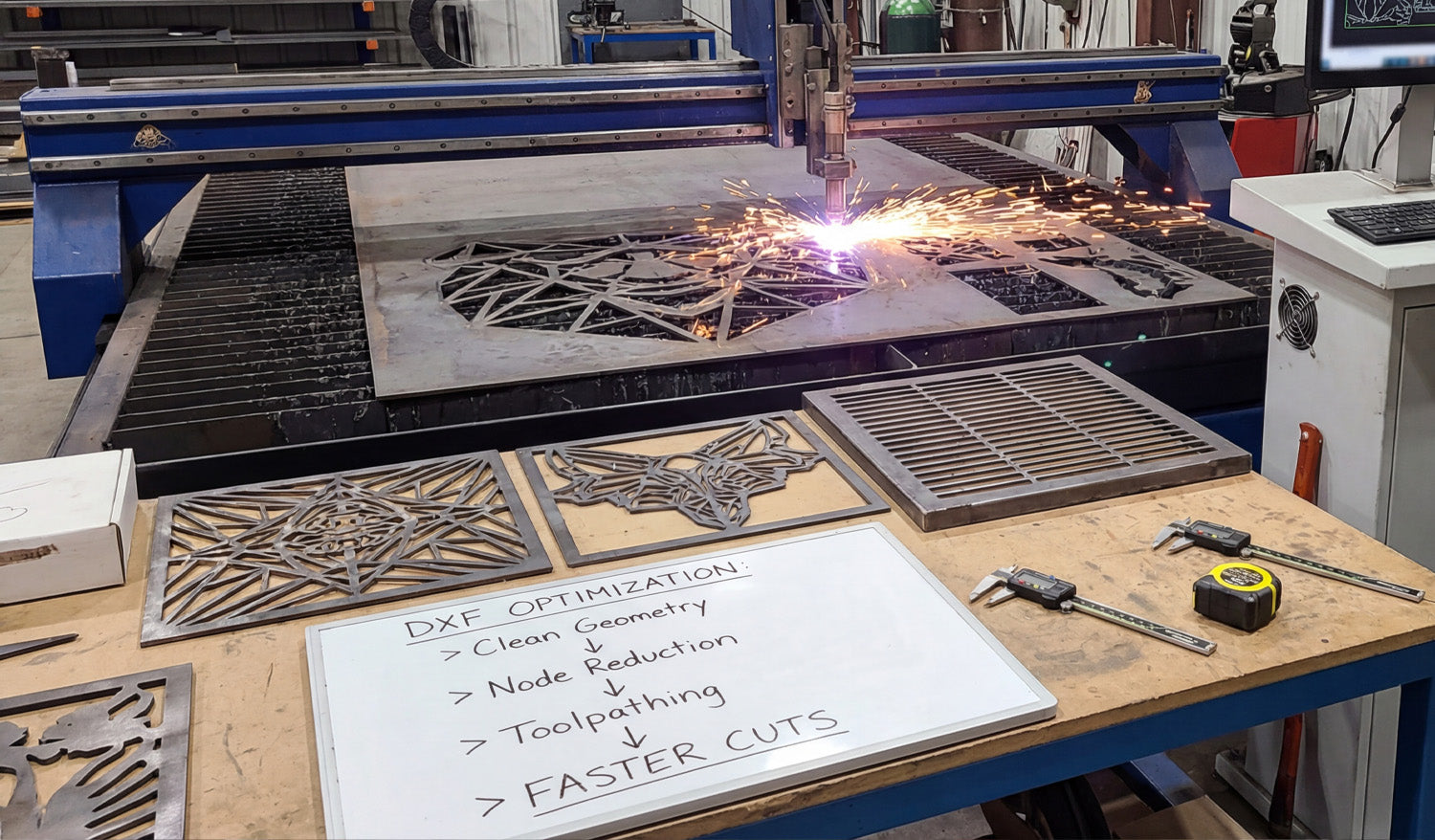
Optimizing DXF files for faster CNC cutting is about reducing wasted motion, cleaning up geometry, and feeding your laser, plasma, or router toolpaths that cut quickly without sacrificing accuracy or edge quality.
Why DXF Optimization Matters for Pro CNC Shops
When you run CNC machines for a living, every second of cycle time turns into real money. Poorly prepared DXF files cause:
- Excessive rapid moves and pierces that slow cycles down.
- Choppy motion that limits feed rates and leaves rough edges.
- Extra setup time in CAM every time a repeat job comes back.
Optimized DXF files let you cut faster at the same quality—or better—while keeping nesting, programming, and re-runs under control.
1. Start with Clean, Lightweight DXF Geometry
Fast toolpaths start with clean data. Before you even open CAM, make sure your DXF is in good shape:
- Delete duplicates: Remove overlapping lines and arcs that cause double cuts.
- Close profiles: Ensure every outer and inner contour is a fully closed loop.
- Strip junk: Remove dimensions, construction lines, points, and tiny fragments.
- Join polylines: Convert short segments into continuous polylines wherever possible.
The goal is a DXF that looks “boring” to CAD but beautiful to CAM—minimal entities, maximum clarity.
2. Control Node Density on Curves for Higher Feed Rates
Too many nodes on a curve slow the machine down. The controller has to process every point, which kills acceleration.
- Use “simplify” or “optimize curve” tools to reduce node count on arcs and splines.
- Replace traced, stair-stepped outlines with true arcs and circles where possible.
- Focus on decorative areas first—logos, scrollwork, and filigree usually contain the worst offenders.
Smoother geometry translates into smoother motion, allowing you to push feeds higher without jerky movement or visible facets.
3. Design with Toolpath Strategy in Mind
DXF optimization is not only about shape—it is about how the machine will move through those shapes.
- Favor long continuous paths: Merge small adjacent segments into single profiles so the tool stays down longer.
- Avoid needless breaks: Don’t split contours just because it is convenient for drawing; every break becomes a stop.
- Eliminate “micro features”: Tiny zigzags, micro tabs, and decorative spikes add time but no value.
Think like the machine: every start, stop, and direction change costs you time. Draw your DXF so the cutter can flow.
4. Use Layers to Drive Faster CAM Setup
Pros cut the same types of parts over and over. Layers let you standardize your CAM workflow so you are not reprogramming from scratch.
- Create a consistent layer set: OUTER_CUT, INNER_CUT, ENGRAVE, MARK, REF.
- Put each entity on the correct layer as you design or clean the DXF.
- Build CAM templates that auto-map layers to tool, speed, and cut rules.
When your DXF files arrive layered correctly, programming becomes a few clicks instead of a fresh setup for every job.
5. Nest for Speed, Not Just Scrap Reduction
It is tempting to chase maximum material usage, but sometimes the fastest nest is not the tightest one.
- Align cut direction: Group parts so the machine can run long, continuous passes instead of zigzagging randomly.
- Leave sensible spacing: Enough room to avoid heat distortion (plasma/laser) and collision issues.
- Use pattern repetition: Arrange repeating parts in rows or columns that cut in a logical sequence.
Balanced nesting—good yield plus smart cut paths—often beats ultra-tight nests that force slow, fragmented motion.
6. Reduce Pierces and Retracts in DXF-Driven Jobs
Pierces and retracts are some of the biggest time sinks, especially for plasma and laser cutting.
- Combine islands where possible: Avoid lots of tiny isolated shapes that each require a separate pierce.
- Use slots instead of many small holes when functionally acceptable.
- Design for common-line cutting (shared edges) on plasma/laser to eliminate redundant passes between adjacent parts.
- Minimize micro cutouts: Replace clusters of small decorative holes with fewer, more substantial features.
Every pierce you save shortens the cycle time and extends consumable life at the same time.
7. Simplify Text and Logos for Production Speed
What looks great in a graphic design program can be a nightmare on the table.
- Use production-friendly fonts for cut text—bold, open shapes with minimal islands.
- Convert logos into clean, single-line or silhouette versions instead of ultra-detailed traces.
- Remove micro-details that disappear after paint or powder coat anyway.
The right simplification keeps the look on-brand while cutting minutes off each part.
8. Create Machine-Specific DXF Variants
Pros often run the same design on different machines. A “one-size-fits-all” DXF is rarely truly optimized.
- Maintain variants like _LASER, _PLASMA, _ROUTER with detail tuned to each process.
- Increase minimum feature sizes for plasma; preserve finer details for laser-only versions.
- Adjust internal radii and slot widths to match typical tool diameters on your router or mill.
Machine-specific DXFs let you run faster feeds and more aggressive strategies without worrying about process limitations.
9. Bake Shop Standards into Your DXF Templates
The fastest way to optimize is to stop reinventing the rules. Turn your best practices into DXF templates and design guidelines.
- Define minimum bridge widths, hole diameters, and text heights per machine and material.
- Standardize on a kerf allowance and clearance strategy for tabs and slots.
- Document preferred layer names and colors so everyone in the team uses the same structure.
When designers follow these standards, DXFs arrive on the shop floor already optimized for speed.
10. Build a Proven “Fast-Cut” DXF Library
Once a file is tuned for speed and quality, treat it like gold.
- Save the final, validated version under a clear name like
partname_fastcut_v3.dxf. - Store DXFs, CAM files, and recommended settings together in a project or library folder.
- Use these proven files as the base for new variants (different sizes, hole patterns, or arrays).
Over time, your library of production-proven DXF files becomes a competitive advantage—new jobs program and run much faster.
Quick Pro Checklist for Faster CNC Cutting with DXF
Before you release a job to the floor, confirm:
- ✔ Geometry is clean: no duplicates, gaps, or junk entities.
- ✔ Curves have optimized node counts for smooth, fast motion.
- ✔ Layers map directly to your standard CAM templates.
- ✔ Nests are arranged for logical, continuous cutting—not just tight packing.
- ✔ Pierce count, retracts, and micro features are minimized.
- ✔ Text, logos, and decorative details are simplified for production.
- ✔ Machine-specific variants exist where necessary (laser, plasma, router).
Conclusion
Optimizing DXF files for faster CNC cutting is a mindset as much as a technique. When you design and clean geometry with toolpaths, pierces, nesting, and machine behavior in mind, your laser, plasma, and router tables run faster, parts look better, and every repeat job gets easier to program. For a pro shop, that combination of speed and consistency translates directly into higher throughput and better margins.


