Advanced techniques for editing DXF files let you clean geometry, control detail, and tailor designs for specific CNC machines so you get faster setup, smoother toolpaths, and more reliable results.
Why Advanced DXF Editing Matters for CNC Applications
Basic DXF editing is enough for simple parts, but real CNC work—especially in production—demands more control. When you know how to refine and optimize DXF files at a deeper level, you can:
- Reduce CAM setup time and manual cleanup on every job.
- Improve edge quality by smoothing motion and cutting down on micro-moves.
- Create machine-specific versions that fit laser, plasma, router, or mill workflows.
- Standardize parts so they are easier to reuse, nest, and scale across projects.
Think of advanced DXF editing as “pre-engineering” your files so every downstream step—CAM, nesting, and cutting—runs smoother.
1. Work Non-Destructively: Master vs Production DXF Files
A key advanced habit is separating your “design master” from your “production-ready” DXF files.
- Master file: The clean, fully editable design (often CAD, AI, or SVG) where you keep rich detail and construction geometry.
- Production DXF: A simplified, optimized version tuned for a specific CNC process.
Workflow tip:
- Always save a copy before making heavy optimizations, scaling, or deleting construction lines.
- Keep master and production files in separate folders so shop-floor edits never overwrite your originals.
- Use clear naming, such as panel_master.dwg and panel_laser_3mm_production.dxf.
This non-destructive approach lets you experiment with aggressive optimizations while keeping a “clean source of truth.”
2. Advanced Layer Strategies and Naming Conventions
Layers are not just for organization—they are powerful tools for advanced control of CNC operations.
- Operation-based layers: Separate CUT_OUTSIDE, CUT_INSIDE, ENGRAVE, MARK, and DRILL.
- Depth-based layers: For routing or milling, name layers by depth (for example, POCKET_Z-3, POCKET_Z-6).
- Machine-specific layers: Use LASER_ONLY, PLASMA_ONLY, or ROUTER_ONLY to enable or disable features per machine.
- Reference layers: Put datums, dimension lines, and setup aids on REF layers that never get cut.
When you import a layered DXF into CAM, you can assign feeds, speeds, and cutting order to an entire layer in seconds instead of selecting geometry by hand.
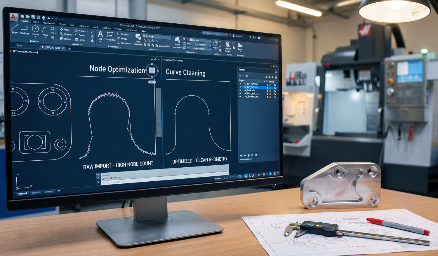
3. Node Optimization and Curve Cleaning
Many DXF files, especially those traced from images, are overloaded with nodes. This causes jerky tool motion and slow cutting. Advanced editing focuses on cleaning curves while preserving shape.
- Simplify curves: Use “simplify” or “fit curve” tools to reduce node count on arcs and splines.
- Replace polylines with arcs: Where possible, convert jagged polyline arcs into real circular arcs.
- Control tolerance: Adjust simplification tolerance so the curve stays visually accurate but lean.
- Target high-density zones: Zoom into corners and tight curves where extra nodes cause the worst slowdowns.
Goal: fewer nodes, smoother motion, and less “stop–go” behavior from your CNC machine without changing the design’s look.
4. Using Boolean Operations for Smart Geometry Editing
Boolean tools—union, subtract, and intersect—are essential for building and editing complex CNC-ready shapes.
- Union (combine): Merge overlapping shapes into a single contour for cleaner outer profiles.
- Subtract: Use shapes to carve holes, windows, and negative spaces out of a base plate.
- Intersect: Extract shared regions from overlapping designs to create new hybrid artwork.
Advanced trick: design “tool blocks” (for example, standard slots, dogbone corners, decorative cutouts) and subtract or union them with main parts to build consistent, reusable geometry across products.
5. Parametric Editing with Constraints and Reusable Blocks
Even though DXF itself is a 2D exchange format, you can use parametric CAD features before export to make editing faster and more precise.
- Constraints: Apply horizontal, vertical, parallel, and concentric constraints so geometry stays aligned when dimensions change.
- Dimensions: Drive important features (slot widths, hole patterns, panel sizes) with numeric parameters.
- Blocks or symbols: Turn common features (bolt circles, hinge cutouts, tabs) into reusable blocks that update everywhere when edited once.
Workflow: edit your parametric sketch or block in CAD, then export a fresh DXF variant for each size, material thickness, or machine.
6. Precision Scaling and Unit Conversion
Advanced CNC users often need to adapt designs between metric and imperial systems or scale designs for different product sizes.
- Use scale factors carefully: 25.4 for inch–mm conversion; verify after scaling with a reference dimension.
- Check hole and slot behavior: Small features may become too tight or too loose after scaling; adjust them manually.
- Maintain aspect ratio: For mechanical parts, scale uniformly; for art pieces, you can sometimes scale height and width separately.
- Add reference geometry: Keep a “this line = 100 mm” or “4 inch” helper so CAM users can confirm scale quickly.
When scaling for different machines (for example, desktop laser vs large-format plasma), always re-check minimum feature sizes against kerf and material thickness.
7. Kerf-Aware Editing Before CAM
Most CAM software handles kerf compensation, but advanced DXF editing can bake in smart geometry choices that make compensation more predictable.
- Thicken critical bridges: Edit thin connections so they remain strong even after kerf is applied.
- Offset inner shapes: For critical fit (tabs, slots, hinges), draw with known offsets that your CAM process expects.
- Standardize hole sizes: Use a small library of hole diameters tuned for your specific tool/kerf instead of random values.
- Pre-plan clearances: Add slight oversize or undersize in the DXF for press-fit, slip-fit, or glue-gap requirements.
This kerf-aware editing reduces the amount of “trial and error” on the machine and gives you more predictable fits, especially for plasma and router work.
8. Topology Fixes: Bridging Islands and Removing Micro Geometry
Complex artwork often contains tiny islands and fragile pieces that do not survive cutting. Advanced DXF editing cleans these up for real-world manufacturing.
- Add bridges: For laser and plasma art, connect floating islands (like the center of letters A, O, P) with small tabs.
- Remove micro cutouts: Delete extremely small shapes that will either burn away or fail to cut cleanly.
- Merge hairline gaps: Join very close edges into solid shapes to avoid creating unintended “hanging” pieces.
- Simplify textures: Replace extremely dense patterns with cleaner, bold shapes that still look good but cut reliably.
These topology edits ensure your beautiful design can actually be cut, handled, and sold as a physical product.
9. Automating DXF Edits with Scripts and Macros
If you handle large volumes of similar DXF files, automation is a powerful advanced technique.
- Batch cleanup: Use CAD macros or external scripts to remove duplicates, close gaps, and standardize layers on many files at once.
- Automatic naming: Generate consistent filenames that include size, material, and version numbers.
- Parametric exports: Drive multiple DXF exports from a single parametric model by looping through different dimension sets.
- Post-processing: Use scripts to convert between DXF versions or strip certain entities before CAM import.
Even simple automation—such as a script that deletes hatches, images, and unused layers—can save hours when you manage a large CNC design library.
10. Creating Machine-Specific DXF Variants
Different CNC machines have different strengths, and advanced users maintain separate DXF variants tuned for each one.
- Laser variant: Keeps finer detail, thin features, and engraving layers that a laser handles easily.
- Plasma variant: Uses thicker bridges, less fine detail, and slightly larger text and small features.
- Router variant: Adjusts inside corners for bit radius, adds dogbone cutouts where needed, and separates pockets by depth.
- Milling variant: Includes precise hole patterns, step pockets, and boundaries for roughing and finishing.
Use shared master geometry and branch off into per-machine DXF files so each machine gets a version that plays to its strengths.
11. Building a Reusable DXF Editing Checklist
Advanced workflows are consistent. A checklist ensures you do not miss critical edits when preparing DXF files.
- ✔ All profiles and pockets are closed (no gaps).
- ✔ Duplicate and overlapping lines removed.
- ✔ Node count optimized on curves and detailed regions.
- ✔ Layers named and structured by operation, depth, and machine.
- ✔ Kerf and minimum feature sizes considered for chosen material and process.
- ✔ Text, logos, and islands bridged where needed for cut-out designs.
- ✔ Unit and scale verified with a reference dimension.
- ✔ Master file saved separately from production-ready DXF.
Over time, this checklist becomes part of your CNC “playbook” and keeps your whole team aligned on how DXF files should look before they reach the machine.
Conclusion
Advanced techniques for editing DXF files go far beyond basic drawing and trimming. By mastering node optimization, layered workflows, boolean operations, kerf-aware geometry, topology fixes, automation, and machine-specific variants, you turn every DXF into a precise set of instructions that your CNC machines can follow with speed and confidence. The payoff is huge: faster programming, smoother cuts, less scrap, and a professional-grade design library that supports serious CNC production.


