Creating multi-layered DXF files for CNC laser projects lets you control cutting, engraving, and marking in a clean, organized way so every pass of the laser is faster, safer, and easier to set up.
What Is a Multi-Layered DXF File?
A multi-layered DXF file is a drawing where different parts of your design are separated onto layers (and often colors). Each layer usually represents a different operation on the laser:
- One layer for through-cuts (outer shapes, holes).
- One layer for engraving (logos, text, fills).
- One layer for scoring or light lines (fold lines, guides).
- Optional layers for reference geometry (construction lines, dimensions).
When you import this DXF into your laser software, you can assign different speeds, powers, and passes to each layer instead of selecting items one by one.
Step 1: Plan Your Laser Operations First
Before you open your CAD or vector software, think about what the laser actually needs to do.
- Will you only cut, or do you also need engraving and scoring?
- Which lines should be deep and dark, and which should be light guides?
- Do you have areas that must be filled (raster-like engraving) versus simple outlines?
Turn that plan into a short list of operations. For example:
- Layer 1 – Cut (through-cut).
- Layer 2 – Engrave (medium power, slower speed).
- Layer 3 – Score (low power, high speed).
- Layer 4 – Reference (not sent to the laser).
Step 2: Set Up Layers in Your CAD or Vector Software
Next, create layers in your drawing program that match your operation plan.
- Create a new file with the correct units (mm or inches).
- Add layers with clear names like L-CUT, L-ENGRAVE, L-SCORE, and L-REF.
- Assign distinct colors to each layer (your laser software can use these colors as mapping targets).
A simple, consistent naming style makes it much easier to reuse and scale your workflow across many projects.
Step 3: Draw and Assign Geometry to the Correct Layers
Now you can build your design and place each element on the right layer.
- Put all outer profiles and holes that should be fully cut through on the L-CUT layer.
- Place logos, decorative outlines, and text you want engraved (not cut through) on the L-ENGRAVE layer.
- Use the L-SCORE layer for fold lines, assembly guides, or light markings.
- Keep construction geometry—centerlines, alignment marks, dimensions—on L-REF so you can hide or delete it before export.
If you move or copy elements, double-check that they stay on the correct layer; many programs quickly show the active layer in the interface.
Step 4: Use Colors to Match Your Laser’s Settings
Most CNC laser controllers let you map colors to different power and speed values. You can use this to make your DXF “machine-ready.”
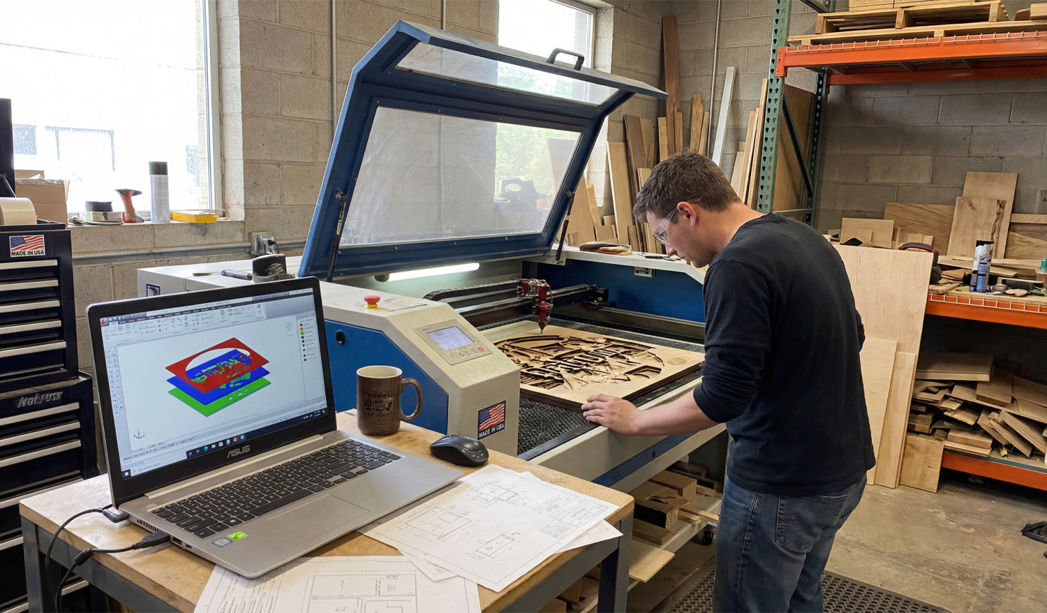
- Assign a unique color to each major layer (for example, red for cut, blue for engrave, green for score).
- Use solid lines only (no fills or hatches) for vector operations.
- Keep the same color scheme across all projects so you can reuse settings in your laser software.
Later, when you import the DXF, you simply tell the laser: “Red lines = cut, 80% power; Blue lines = engrave, 20% power,” and so on.
Step 5: Manage Line Types and Stroke Weights
Line thickness in the DXF does not change the physical kerf of the laser, but it can help you visually organize and avoid mistakes.
- Use a standard thin stroke for all cutting and engraving paths.
- Optionally use dashed or dotted lines on reference layers for construction or fold guides.
- Avoid heavy line weights that may export poorly or confuse your laser software.
Keep in mind that most laser controllers only care about the vector path itself, not the stroke width—so the visual styling is just for your editing comfort.
Step 6: Add Registration and Alignment Marks on Separate Layers
For multi-step or multi-material projects, you may need registration marks to align different passes or colors.
- Create an L-REG layer just for alignment marks (small crosses or circles).
- Place the marks in consistent positions relative to your artwork (corners, midpoints, or known offsets).
- Decide whether these marks should be lightly engraved, cut, or only used for positioning and then removed.
If you engrave and cut in separate jobs or on different materials, matching registration marks makes it much easier to keep everything lined up.
Step 7: Organize Filled Areas vs Outlines
Many CNC laser projects need both vector lines and filled engraving areas (for example, solid logos, badges, or backgrounds).
- Keep outlines and borders on their usual cut/engrave layers.
- For filled areas, create separate fill regions on an engraving layer or assign them a specific color.
- Some workflows convert these fills to hatch patterns or treat them as raster engravings at the CAM stage.
Clearly separating outlines from fill regions in your DXF makes it easier to adjust engraving depth and texture without changing the main shapes.
Step 8: Check Geometry Quality on Each Layer
Before exporting, zoom in and make sure each layer is clean and laser-ready.
- Verify that all cut paths are closed loops with no gaps.
- Check that engraving and scoring lines do not have duplicate or overlapping segments.
- Reduce unnecessary nodes on curves so the laser head can move smoothly.
- Delete or hide reference layers that should not be sent to the laser (unless your software can ignore them by layer or color).
A quick per-layer review saves you from surprises at the machine and reduces setup time in the laser software.
Step 9: Export a Clean Multi-Layer DXF
When your design is ready, it is time to export a DXF file that preserves your layer structure.
- Use Save As or Export and choose a DXF version compatible with your laser software (often R12/R14 works well).
- Make sure the option to include layers and colors is enabled.
- Give the file a clear name that hints at material and size, such as multi_layer_sign_acrylic_300mm.dxf.
After export, open the DXF in a viewer or your laser CAM software to confirm that layers and colors carried through correctly.
Step 10: Map Layers to Laser Settings in Your Controller
In your laser control software, import the DXF and connect each layer or color to the correct cutting parameters.
- Assign cut layers to high power, medium speed, and through-cut mode.
- Assign engrave layers to lower power, slower speed, and appropriate line or fill mode.
- Assign score layers to very low power, fast speed for light surface marks.
- Decide whether registration or reference layers should be ignored, scored, or engraved lightly.
Once you dial in good settings, save them as presets so the next multi-layer DXF with the same color scheme can be set up in seconds.
Common Mistakes When Creating Multi-Layer DXF Files
Watch out for these issues that can cause confusion or wasted material:
- Mixing operations on one layer: Putting cut and engrave lines together on the same layer makes setup slower and riskier.
- Inconsistent color usage: Changing which color means “cut” from project to project leads to mistakes.
- Forgotten reference geometry: Leaving dimensions or construction lines active in the DXF can create unwanted marks.
- Overlapping cut and engrave paths: Duplicate geometry on different layers can cause double passes in the same location.
Practical Tips for Building a Reusable Multi-Layer Workflow
- Use the same layer names and colors across all projects.
- Create a template file with layers, colors, and line types preconfigured.
- Write a short legend in the notes: which layer = which operation and typical power/speed.
- Save “test coupons” in your library that use all your standard layers so you can quickly re-tune settings on new materials.
Over time, this consistency turns multi-layer DXF setups into a fast and reliable part of your CNC laser workflow.
Conclusion
Creating multi-layered DXF files for CNC laser projects is one of the best ways to keep your designs organized and your jobs easy to run. By planning your operations, setting up clear layers and colors, assigning the right geometry to each layer, and exporting a clean DXF, you give your laser software everything it needs to apply precise power, speed, and order to every line. The result is less setup time, fewer mistakes, and laser projects that move smoothly from design to finished part.


