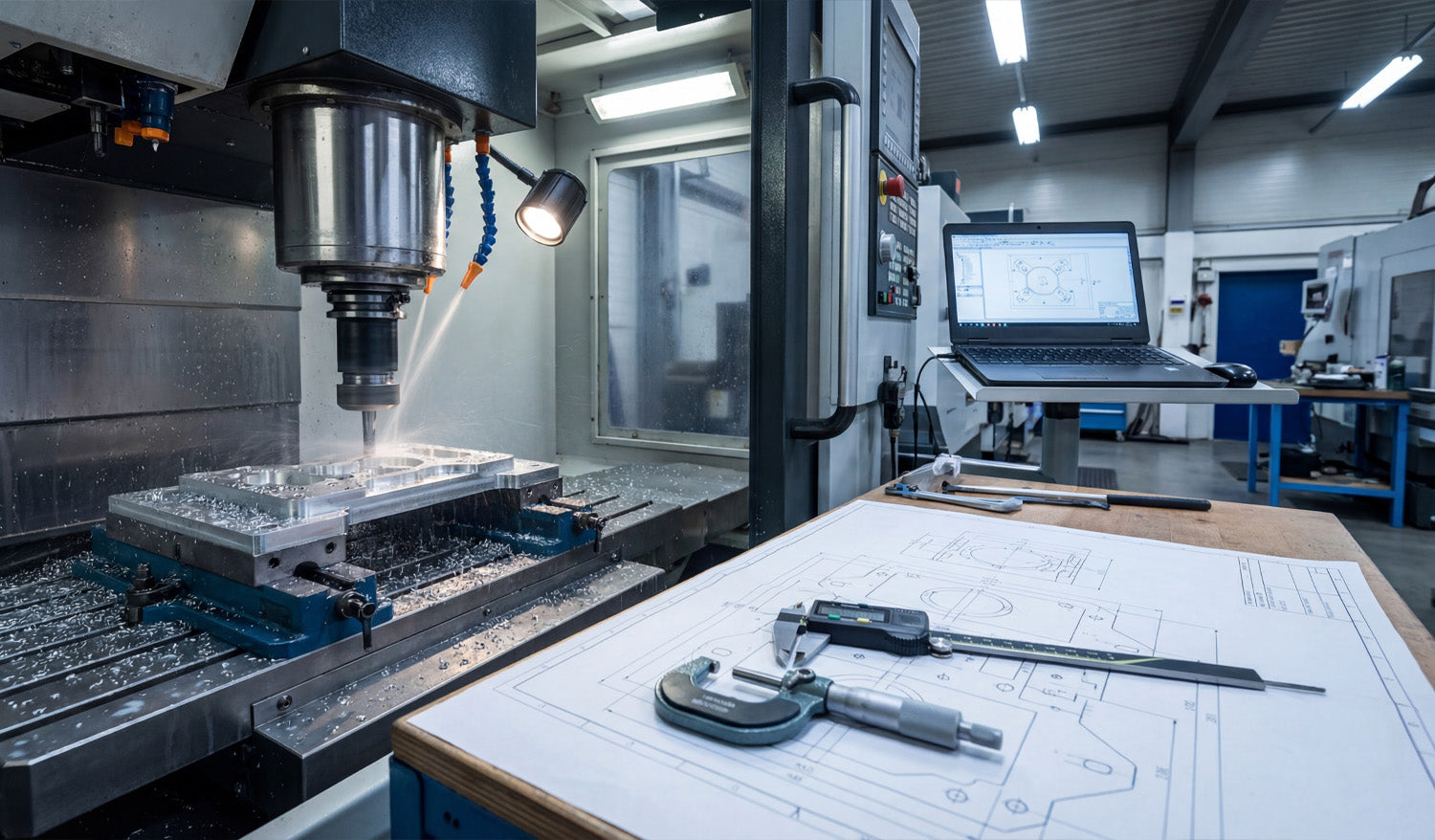
Precision in CNC machining is not an accident; it is the result of a rigorous alignment between your digital file and your physical machine. As captured in the photo above, the journey from a raw block of aluminum to a perfectly milled component involves three critical pillars: a clean CAD/CAM setup, precise physical verification using calipers and micrometers, and, most importantly, a flawless source file. Whether you are running a heavy-duty Vertical Machining Center (VMC) or a high-precision desktop router, the rule remains the same: the machine can only be as accurate as the DXF file you feed it.
The Triangle of Precision: Examining the Workflow
In the workshop image, you see the complete ecosystem required for high-tolerance manufacturing. Let's break down how these elements work together to create profitable parts:
- The Digital Twin (Laptop): The screen shows the 2D geometry (the DXF) being transformed into toolpaths. This is where errors usually start. If your DXF file has overlapping lines or unjoined vector nodes, your CAM software will generate erratic G-Code.
- The Physical Verification (Calipers & Blueprint): On the workbench, you see digital calipers and a micrometer sitting on top of a technical drawing. These tools are the judge and jury. They verify that what you downloaded matches what you cut.
- The Execution (CNC Mill): The machine in the background is removing material at high speed. There is no "undo" button here. This is why validating your files before hitting the green button is essential.
Why DXF Files Matter for 2.5D Milling
While many people associate DXF files strictly with 2D cutting (like plasma or laser), they are the backbone of projected 2.5D milling. When you are machining a bracket or a mechanical part, you import a DXF to define the pockets, contours, and drill locations.
Using high-quality designs, such as those found in our Full Access Bundle, ensures that your geometry is mathematically perfect. A perfect circle in a DXF means a perfect bore on the machine. A segmented or low-resolution curve will result in "faceting" on your finished part, requiring hours of manual sanding and polishing to fix.
From Prototype to Production
The setup in the photo represents a "First Article Inspection." The operator is likely cutting the first piece to verify tolerances before running a full batch. To streamline this process in your own shop:
- Test with Free Files: Before committing to expensive material, run a test cut using one of our Free DXF Designs to calibrate your machine's backlash and kerf/tool offset settings.
- Check the Blueprint: Always compare the dimensions in your CAM software against your required specs. DXF files are unitless; ensure you aren't cutting millimeters as inches!
- Measure Twice: Use your calipers immediately after the roughing pass. If the dimensions are off, check if the issue is mechanical (tool wear) or digital (incorrect file scaling).
Building a Business on Accuracy
Customers pay for precision. Whether you are selling automotive parts or custom metal art, the ability to deliver exact replicas time and time again builds trust. By starting with professional-grade vector files, you eliminate the biggest variable in the equation.
If you are unsure if your current software supports our file types, visit our FAQ Page. For those looking to sell the parts they manufacture, please review our License Agreement to understand your rights. Precision starts with the download.


