Transforming a digital concept into a tangible metal part is the ultimate goal of every CNC fabricator, yet the gap between a design on a screen and the sparks flying in the shop is often where beginners struggle. The process requires a seamless transition from the initial CAD design to a clean DXF file, and finally to the CNC machine that executes the specific cutting or marking commands. By understanding how to organize your digital layers and optimize your files, you ensure that your plasma or laser cutter operates efficiently, reducing wasted material and maximizing profit on every custom part you produce.
The 4-Step Workflow: From Idea to Industrial Part
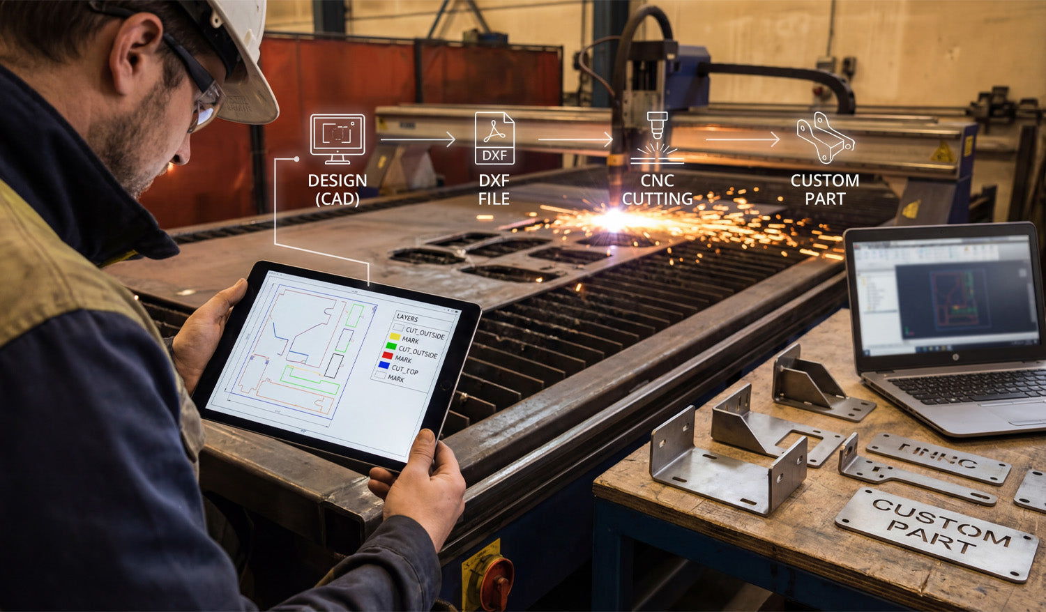
As shown in the workflow graphic above, successful fabrication isn't magic; it is a structured process. Whether you are running a garage workshop or a full-scale industrial operation, the path remains the same:
- 1. Design (CAD): It starts with imagination and geometry. Using CAD software, you define the dimensions and shape of your part. This is where accuracy counts the most.
- 2. DXF File Creation: This is the universal language of CNC. Converting your design to a DXF (Drawing Exchange Format) bridges the gap between your computer and the machine controller.
- 3. CNC Cutting: The machine interprets the vector data from the DXF. If the file is clean, the torch or laser follows the path precisely.
- 4. The Custom Part: The result is a physical product—like the heavy-duty brackets shown on the workbench—ready for assembly or sale.
Why Layering Matters: A Look at the Tablet
If you look closely at the tablet in the image, you will see a crucial detail that separates amateurs from pros: Layer Management. The screen displays different colors for different operations (Yellow for "MARK", Green/Blue for "CUT_OUTSIDE").
Your CNC machine needs to know the difference between cutting a hole through the material and simply etching a part number or bend line onto the surface. By separating these geometries into specific layers within your DXF file, you tell the CAM software exactly what to do.
Pro Tip: Always set your cut order to etch/mark first, cut interior holes second, and cut the exterior perimeter last. This prevents the part from shifting on the table before the internal work is finished.
Turning Sparks into Profit
The brackets and custom parts sitting on the table in the photo represent revenue. In the world of CNC, time is money. Every minute you spend fixing bad nodes or unconnected lines in a DXF file is a minute the machine isn't cutting.
To scale your business, you need a library of files that are "cut-ready." This allows you to say "yes" to clients faster and move straight to production. Whether you are selling automotive brackets, custom signage, or structural components, the quality of your source file dictates the quality of your product.
For those looking to skip the design headache and start cutting immediately, accessing a verified library is a game changer. You can explore our vast collection of designs in our Full Access Bundle, which provides thousands of tested, layer-optimized files ready for your machine.
Start with the Right Files
If you are new to this workflow, don't be intimidated. Start by testing your machine's settings with simple geometries. You can practice with reliable designs by downloading from our Free DXF Files section. Mastering the link between the "Design" and the "Cut" is the most valuable skill you can develop in the CNC industry.


