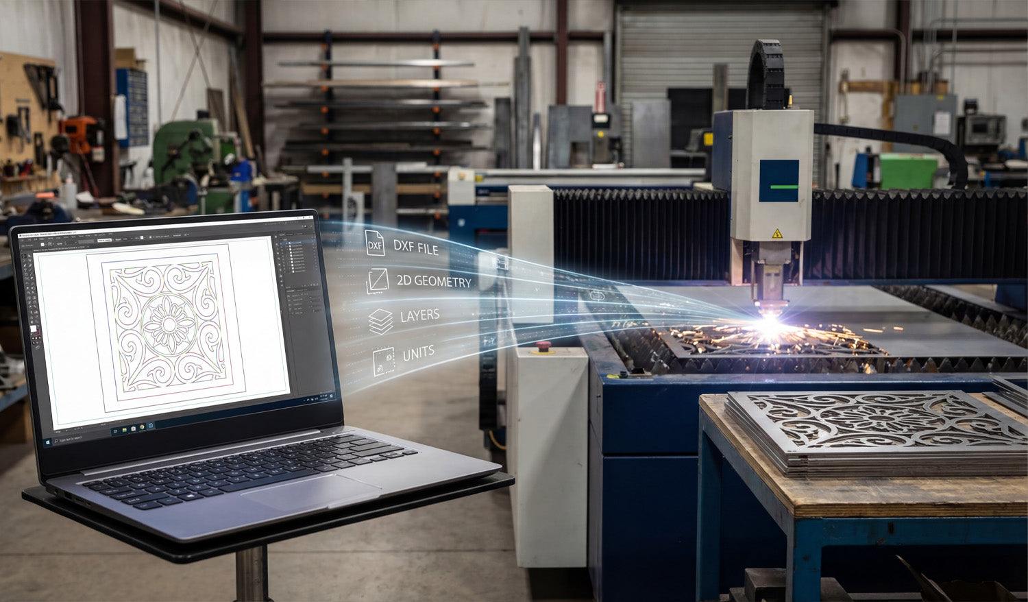
DXF files act as the “common language” between your design software and CNC cutting machines, carrying clean 2D geometry, layers, and units so lasers, plasmas, routers, and water-jet tables know exactly where to move, where to pierce, and what to cut.
What Is a DXF File in the CNC World?
DXF (Drawing Exchange Format) was created to let different CAD programs share vector drawings. In CNC cutting, that same format became the standard way to describe 2D shapes like profiles, holes, slots, and engravings.
- Vector-based: DXF stores lines, arcs, circles, and splines as precise math, not pixels.
- Neutral format: It is not tied to one brand of CAD or CAM software.
- 2D-first: Perfect for flat parts cut on laser, plasma, router, and water-jet machines.
Instead of sending screenshots or photos to the shop floor, you send a DXF file that the machine can interpret without guesswork.
Where DXF Files Sit in the CNC Workflow
To understand the role of DXF files, it helps to look at a typical CNC cutting workflow from idea to part:
- Design: You create or edit a part in CAD or a vector design tool.
- Export: You save the 2D geometry as a DXF file.
- CAM / Nesting: CAM software imports the DXF, creates toolpaths, and nests parts on sheets.
- CNC Machine: The cutting machine runs code generated from those toolpaths.
The DXF file is the bridge between “design space” and “machine space,” carrying only the essential 2D information the cutter needs.
How DXF Files Communicate Shape and Size
CNC cutting machines do not care about colors, gradients, or photos—they care about paths. DXF files provide exactly that.
- Coordinates: Each line and arc has precise start and end points.
- Units: Geometry is defined in millimeters or inches (depending on how the file is created).
- Closed profiles: Outer shapes and inner cutouts can be recognized as complete loops for cutting.
When these paths arrive in CAM, the software can easily turn them into toolpaths: inside cuts, outside cuts, and outlines for engraving.
The Role of DXF in Different CNC Cutting Machines
Almost every 2D CNC cutting process can use DXF files, but each machine type benefits in slightly different ways.
Laser Cutting Machines
- Lasers use DXF geometry to cut very fine details in wood, acrylic, and thin metals.
- Separate layers or colors in the DXF can map to cutting vs engraving power settings.
- Clean, smooth curves in DXF mean fewer pauses and cleaner edges on the finished part.
Plasma Cutting Tables
- Plasma machines rely on DXF files to define bold shapes, holes, and slots in steel, stainless, and aluminum.
- Properly designed DXF files help avoid blown-out small features and irregular holes.
- DXF-based nests allow you to fit many heavy parts onto a sheet with efficient cut paths.
CNC Routers
- Routers use DXF files for cutting plywood, MDF, plastics, and soft metals.
- DXF geometry defines pockets, profiles, and drill hole locations.
- Tool diameters and step-downs in CAM are based on the exact geometry imported from DXF.
Water-Jet Cutting Machines
- Water-jets use DXF files to cut thick or heat-sensitive materials like stone, composites, and metals.
- Accurate shapes in DXF help maintain tight tolerances without heat distortion.
In all of these cases, the machine type changes—but the DXF remains the standard way to describe the cut path.
DXF Layers: Organizing Operations for the Machine
Beyond just shapes, DXF files can store layers that help you tell the machine what each path should do.
- CUT_OUTSIDE: Outer profiles for final part edges.
- CUT_INSIDE: Holes, slots, windows, and internal cutouts.
- ENGRAVE / ETCH: Logos, text, part numbers, bend lines, or weld marks.
- REFERENCE: Centerlines, dimensions, and construction geometry not meant to be cut.
In CAM or controller software, you can map these layers to different tools, speeds, and power levels, turning one DXF into a complete cutting plan.
DXF Files and Kerf Compensation
DXF geometry describes the “ideal” shape. The machine then has to account for kerf—the width of the cut made by a laser beam, plasma arc, or router bit.
- CAM software uses DXF profiles to calculate offset toolpaths inside or outside the line.
- For tight fits, DXF-based dimensions must be accurate so kerf compensation produces the correct final size.
- When you learn how your machine behaves, you can build that knowledge into your DXF designs (for example, slightly oversizing small holes).
In this way, DXF files play a direct role in how precise and repeatable your finished CNC parts will be.
DXF as a Shared Language Between Teams and Tools
In real shops, designers, programmers, and machine operators often use different software. DXF makes it possible for everyone to work together.
- Designers create parts in their favorite CAD or graphics tool and export as DXF.
- CAM programmers import the DXF into nesting or toolpath software.
- Operators run the resulting CNC code on different machine brands.
Because DXF is widely supported, you are not locked into one software ecosystem. You can swap machines, change CAM packages, or bring in outside help without needing to redraw your entire library.
DXF Files in Prototyping vs Production
The role of DXF files shifts slightly depending on whether you are making a one-off prototype or running a large batch.
Prototyping
- DXF files let you quickly iterate on shapes, hole positions, and clearances.
- You can tweak a few dimensions, export a new DXF, and cut another test part in minutes.
- Once the shape works, you save that DXF as your “approved” geometry.
Production
- DXF files become part of a controlled library—each with a drawing number and revision.
- CAM and nesting templates are built around standardized DXF layers and naming.
- Repeat orders use the same DXF geometry, ensuring consistent parts across batches and machines.
In both scenarios, DXF files are the geometry source of truth that the rest of the CNC process depends on.
Handling Customer-Supplied DXF Files
Many shops receive DXF files directly from customers. In those cases, the DXF’s role includes both opportunity and responsibility.
- Opportunity: You can skip the design stage and move straight into checking, cleaning, and programming.
- Responsibility: You must verify units, scale, closed paths, and feature sizes before cutting.
- Communication: If something is off—like hole sizes or material thickness—you use the DXF as a clear reference when talking to the customer.
A well-prepared customer DXF can go from inbox to machine very quickly; a poor one needs editing before it is safe to use.
Common DXF Issues That Affect CNC Machines
Because DXF files sit between design and cutting, problems in the file often show up as problems on the machine.
- Open contours: Paths that are not fully closed can be skipped or misinterpreted by CAM.
- Duplicate entities: Overlapping lines cause double cuts, rough edges, and wasted time.
- Too many nodes: Overly dense curves make machines slow down and produce faceted edges.
- Wrong units: Files drawn in inches but loaded as mm (or vice versa) create parts at the wrong size.
Understanding these issues helps you see why good DXF practices are so important to CNC machine performance.
Why DXF Files Still Matter in Modern CNC Shops
Even as 3D CAD and more advanced formats grow, DXF files remain crucial for flat cutting work.
- Most flat parts—brackets, gussets, panels, signs, fixtures—are still cut from 2D profiles.
- CAD users can easily extract 2D views from 3D models and export them as DXF.
- Legacy designs and old projects are often stored as DXF and still cut perfectly today.
This long-term stability is why so many shops still center their 2D cutting workflows on DXF files.
Conclusion
DXF files play a central role in CNC cutting machines by translating design intent into machine-ready geometry that lasers, plasmas, routers, and water-jets can understand. They carry the outlines, holes, layers, and units that CAM systems need to build toolpaths and that operators rely on for repeatable, accurate parts. When you master how DXF files fit into the CNC workflow—from clean design and layer management to kerf-aware geometry—you gain tighter control over quality, speed, and consistency across every cutting project.


