CNC & DXF Design Guides
CNC & DXF Design Guides
Decorative Ornamental Double Gate DXF File for CNC Plasma & Laser Cutting
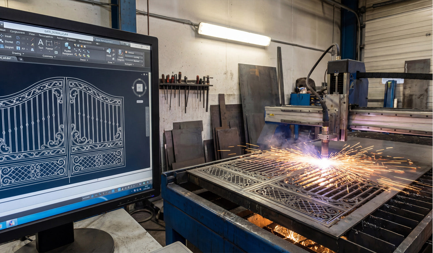
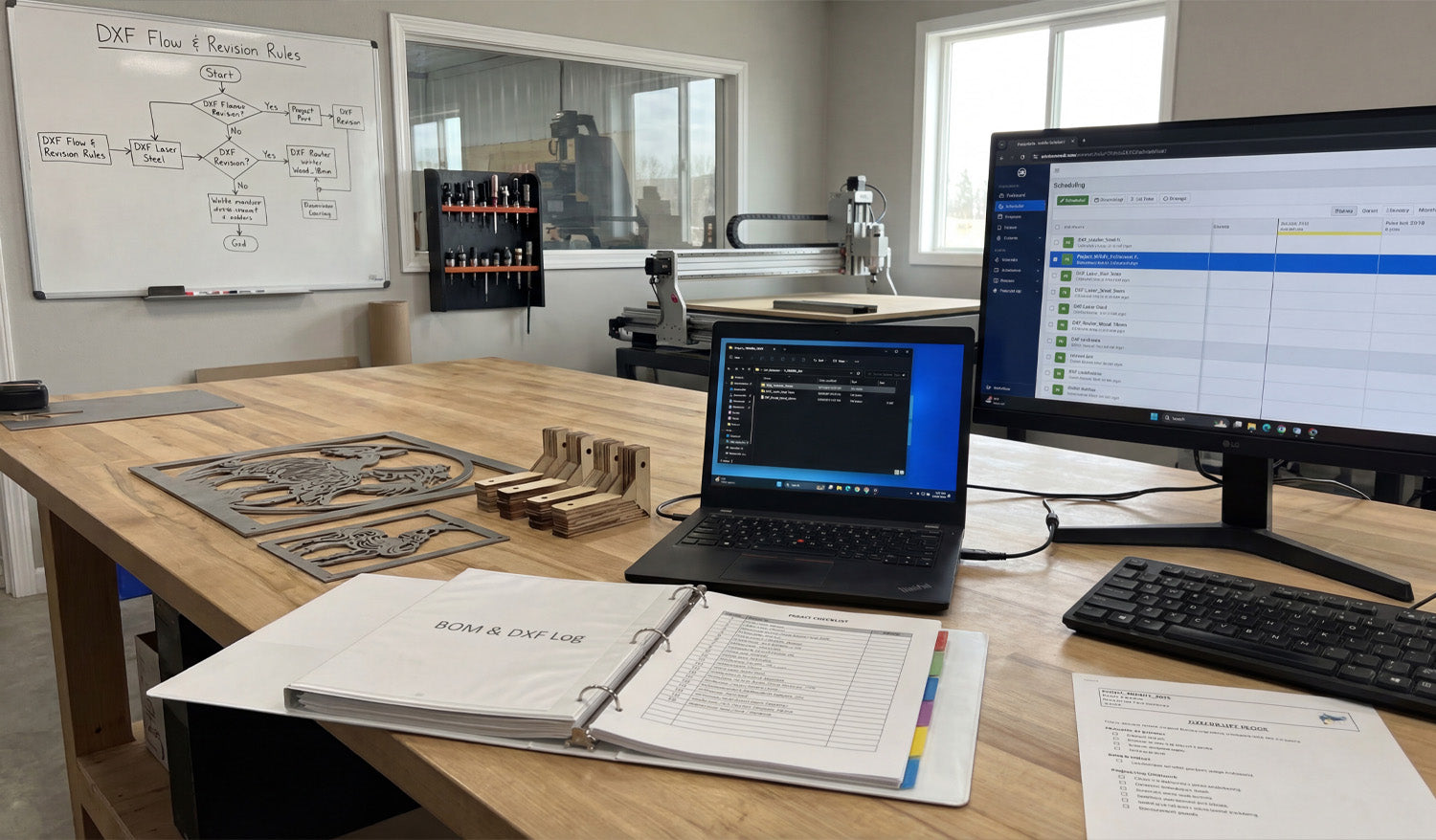
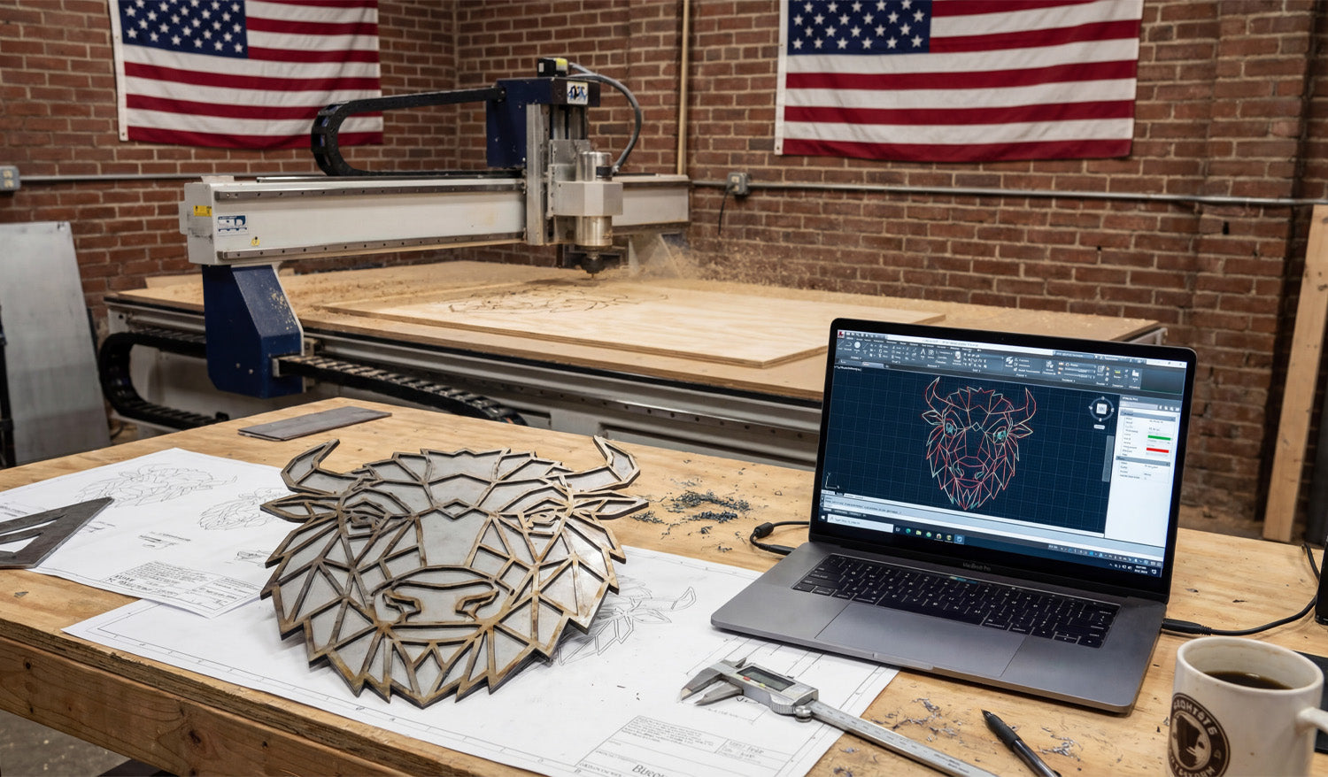
In the CNC world, few projects deliver higher profit margins than custom ornamental gates. With the right DXF file, a simple sheet of steel can instantly transform into a premium architectural feature that homeowners are willing to pay top dollar for. Before we dive into the workflow, this guide will show you how professional, ready-to-cut gate designs turn digital sketches into real metalwork—and how these high-demand projects can become one of the most reliable revenue streams for your CNC business. From Screen to Spark: How to Turn Gate Designs into High-Profit Metalwork Look at the image above. On the left, you see a precise, digital blueprint sitting on a CAD screen. On the right, that digital dream is becoming a fiery reality as a CNC plasma cutter slices through steel to create a stunning ornamental gate. As a CNC specialist, I see more than just sparks and software here; I see a bridge between creativity and a highly profitable business. Today, let’s talk about how high-quality DXF files transform raw metal into high-ticket architectural elements. The Power of the Right File For anyone running a CNC business—whether you use plasma, laser, or waterjet—the starting point is always the design. You can have the most expensive machine in the shop, like the one in the photo, but if your source file is bad, your cut will be bad. This specific gate design features intricate scrollwork and safety bars. Designing this from scratch takes hours of skilled CAD work. That is where we come in. By using ready-to-cut DXF files, you skip the tedious drawing phase and jump straight to production. This means you can say "yes" to a customer in the morning and have the metal cut by the afternoon. Why Gates and Fences? (The Business Angle) Why did I choose to showcase a gate? Because in the world of custom metal fabrication, architectural metalwork is king. Homeowners and developers are constantly looking for "curb appeal." A standard wooden fence is boring. A custom-cut steel gate, however, adds luxury and security. Low Material Cost: You are buying standard sheets of steel or aluminum. High Resale Value: Once processed into a finished gate, the value increases exponentially. You are selling art, not just metal. Technical Tip: Clean Lines Matter Notice the detail on the screen in the photo. When you are cutting intricate patterns like these scroll designs, your DXF file needs to be flawless. No Open Contours: The laser needs a continuous path. Reduced Node Count: Too many nodes make the machine stutter, causing rough edges. Kerf Compensation: Our designs are optimized to ensure that fine details don't burn away during the cut. We test our files to ensure that what you see on the monitor is exactly what you get on the table. Start Cutting Today If you are looking to expand your portfolio with high-quality gates, railings, or privacy screens, you don't need to hire a designer. We have done the heavy lifting for you. Want to test our quality? Download some of our Free DXF Files here to see how they run on your machine. Ready to go big? If you want instant access to our entire library of designs—including gates, wall art, fire pits, and more—check out our Full Access Bundle. It is the smartest investment for a growing CNC shop. If you have questions about file compatibility or cut settings, feel free to check our FAQ page or drop us a line at info@dxffilesforcnc.com. Let's turn those sparks into success!
How to Maximize Your CNC Cutting Efficiency Using DXF Files
Maximizing CNC cutting efficiency using DXF files starts long before the machine turns on. When your drawings are clean, organized, and designed with the cutter in mind, you get shorter cycle times, less scrap, and repeatable jobs that are easy to run again and again. DXF Files as the Foundation of an Efficient Workflow DXF files are more than just “something the CAM software can open.” They are the digital blueprint that defines: How many moves your machine will make. How often it pierces, retracts, and rapids. How easily you can nest, quote, and rerun jobs later. When you design and clean DXF files with efficiency in mind, every downstream step—from nesting to cutting—gets faster. 1. Design Parts to Be CNC-Friendly from the Start Efficient cutting begins at the design stage. Ask yourself, “How will the machine move through this geometry?” Favor continuous contours: Long, smooth paths are faster than many tiny segments and islands. Avoid unnecessary complexity: Decorative spikes, jagged micro-details, and dense hatching slow motion and add no real value. Size features realistically: Keep holes, tabs, and slots large enough for your kerf and tools so they cut cleanly at normal speeds. A design that “looks amazing” but forces the machine into stop-start motion is not efficient. Simpler, cleaner geometry usually wins in real production. 2. Clean DXF Geometry Before It Reaches CAM Messy DXF files cause programming friction and longer run times. A few minutes of cleanup in CAD can save hours on the table. Remove duplicate lines and overlapping arcs that cause double cuts. Close all open contours so CAM recognizes full profiles instantly. Delete dimensions, hatches, and stray points that do not contribute to cutting. Convert splines into polylines or arcs that your CNC software can process smoothly. Clean geometry means faster toolpath calculation and smoother motion, which directly improves cutting efficiency. 3. Optimize Curves for Smooth, High-Speed Motion CNC controllers love smooth curves and hate thousands of tiny segments. The way curves are stored in your DXF affects how fast you can run. Use “simplify” tools to reduce node count on curves without changing the overall shape. Replace irregular traced outlines with true arcs and circles wherever possible. Pay extra attention to logos and decorative patterns—these are where needless nodes usually pile up. The smoother the math behind each curve, the more confidently you can increase feed rates without chatter or visible faceting. 4. Use Layers to Automate Fast CAM Setup Efficient shops do not rebuild CAM strategies from scratch every time. They use DXF layers to drive automated toolpath rules. Standardize layers like OUTER_CUT, INNER_CUT, ENGRAVE, and MARK. Assign entities to the right layer as part of your normal drawing process. Create CAM templates that map each DXF layer to a tool, speed, and cut rule. With this system, importing a well-layered DXF becomes a two-minute job: choose the template, confirm the toolpaths, and you’re ready to nest and post. 5. Design Parts for Efficient Nesting Good DXF design makes nesting faster and more material-efficient at the same time. Keep parts rectangular or gently contoured where possible—these nest easier than random shapes. Consider common-line cutting for compatible parts to reduce total cut length. Avoid unnecessary protrusions that force awkward gaps between parts. When your DXF parts are nesting-friendly, you spend less time manually arranging layouts and more time cutting full sheets. 6. Reduce Pierces and Retracts in Your DXF Strategy Each pierce and retract adds time, especially for plasma and laser cutting. Smart DXF design can cut those counts down. Combine small features into shared shapes instead of many isolated cutouts. Use slots instead of clusters of holes when functionally acceptable. Group similar features so CAM can cut them in one continuous sequence instead of jumping around the sheet. Fewer pierces and retracts mean less wear on consumables and shorter overall cycle times. 7. Match Detail Level to Machine and Material Pushing ultra-fine detail through a machine that cannot support it is a direct hit to efficiency. For plasma, avoid micro details that will burn out or warp; use bold, simplified geometry. For routers, keep gaps wider than your smallest tool diameter so you can run at normal speeds. For lasers, you can keep more detail, but still avoid fragile bridges that slow motion or break during handling. Designing to the realistic limits of your setup lets you cut at efficient feeds without babysitting every move. 8. Standardize DXF Naming and Storage for Fast Reuse Efficiency is not only about individual cuts—it is also about how quickly you can rerun profitable jobs. Include project code, material, thickness, and revision in the DXF filename. Store DXF files in folders by process (laser, plasma, router) and material (steel_3mm, birch_6mm, etc.). Keep a separate library of “production-ready” DXFs that have already been tested on the machine. When a repeat order comes in, you should be able to grab the exact DXF you used last time and go straight to nesting. 9. Build a “Proven Settings” Library Linked to DXF Files After you dial in a DXF and CAM strategy that cuts fast and clean, capture that knowledge so you do not start from zero again. Save CAM files and notes alongside the DXF: feeds, speeds, power, pierce heights, and gas or air settings. Mark which designs are safe for high-speed runs and which ones require conservative settings. Use that data when quoting: efficient DXF + proven settings = more accurate time estimates. Over time, your best DXF designs become a library of fast, reliable recipes you can plug into your schedule whenever machines have capacity. 10. Run Small Tests to Validate Efficient Strategies Pushing for efficiency is always a balance between speed and quality. Test cuts help you find that sweet spot. Use offcuts or small sections of a nest to try higher feed rates and lower cycle times. Watch for signs of overheating, edge quality loss, or dimensional drift. When a new combination of DXF cleanup + CAM strategy works well, lock it in as your new standard for similar parts. This method lets you gradually increase efficiency without gambling full sheets of material on untested settings. Conclusion To maximize CNC cutting efficiency using DXF files, treat your drawings as more than just artwork—they are the engine behind your entire workflow. Clean geometry, smart use of layers, nesting-friendly shapes, reduced pierces, and consistent naming all add up to shorter programming time and faster cutting on the shop floor. When you optimize DXF files with the machine in mind, every job becomes easier to run, easier to repeat, and more profitable.
How to Use DXF Files for Laser and Plasma Cutting Projects
Using DXF files for laser and plasma cutting projects is all about starting with clean vector artwork, setting up the right layers and scale, and then turning those paths into safe, efficient toolpaths your machine can follow without surprises. Why DXF Files Work So Well for Laser and Plasma Cutting Laser and plasma cutters both love vector geometry. DXF (Drawing Exchange Format) files store shapes as exact lines, arcs, and curves instead of pixels, which makes them ideal for 2D cutting. Accurate shapes: Holes, slots, and contours are defined by coordinates, not by fuzzy image edges. Easy scaling: You can resize designs to fit different sheet sizes without losing quality. Wide support: Almost every CAD, CAM, and controller software understands DXF. Whether you are cutting intricate wall art on a laser or thick steel parts on a plasma table, DXF files give you a reliable starting point. Step 1: Plan the Project Around Your Machine and Material Before opening any DXF file, think about the real-world setup you will use: Machine type: Laser for fine, clean edges; plasma for thicker, structural metal work. Material: Wood, acrylic, and thin metals for lasers; mild steel, stainless, or aluminum for plasma. Thickness: This affects minimum detail size, kerf width, and cutting speed. Knowing these basics up front helps you choose or adjust DXF designs that will actually cut well on your specific machine. Step 2: Choose or Create DXF Files That Fit the Process You can either draw DXF files yourself or use ready-made designs, but in both cases, think “laser/plasma friendly.” For lasers: Fine detail is possible, but avoid hairline bridges that can burn away. For plasma: Use bold shapes, thicker webs, and avoid tiny interior cutouts that may deform or blow out. For both: Keep the overall design simple enough that it cuts cleanly and quickly. Look for DXF designs that mention being tested on laser or plasma cutters, or adapt existing artwork to better match your process. Step 3: Open the DXF and Check Scale and Units One of the most common early mistakes is wrong scale. Always verify the size as soon as you import the DXF. Confirm whether the file was designed in mm or inches. Use a measurement tool in your CAD/CAM software to check a known dimension. If needed, scale once to correct size—then lock that in and avoid repeated scaling. Getting the scale right at the beginning saves you from discovering that a “10 inch sign” actually came out 10 cm wide. Step 4: Clean Up the Geometry for Laser and Plasma Laser and plasma toolpaths depend on clean, connected geometry. Before generating any code, inspect and tidy your DXF. Close all loops: Make sure outside profiles and inside cutouts are fully closed paths. Remove duplicates: Delete overlapping lines and arcs that would cause double cutting. Eliminate tiny fragments: Get rid of random points, micro shapes, and leftover construction lines. Join polylines: Where possible, join segments into continuous polylines to improve motion. Clean geometry helps the CAM software generate predictable, smooth toolpaths for both laser and plasma cutting. Step 5: Use Layers to Separate Cutting and Engraving Most DXF-based workflows work best when you use layers or colors to tell the machine what each line should do. Create layers such as OUTER_CUT, INNER_CUT, ENGRAVE, and MARKING. Put outside contours on OUTER_CUT and holes/slots on INNER_CUT. Place engraving lines and text on ENGRAVE, and layout marks or bend lines on MARKING. Keep dimensions and centerlines on a reference layer that will never be cut. Later, in CAM or your controller software, you can map each layer to different power, speed, or cutting depth settings. Step 6: Adapt Detail Level for Laser vs Plasma Laser and plasma cutting respond differently to fine detail, even when they use the same DXF. Using DXF Files for Laser Cutting Lasers can handle small text and intricate patterns, especially in thin materials. Still avoid ultra-thin bridges that might char, warp, or snap easily. Use separate layers for engraving vs cutting, so you can assign different power levels. Using DXF Files for Plasma Cutting Use bolder shapes and keep narrow webs wider than your kerf plus a safety margin. Simplify tiny internal details that plasma cannot hold reliably at your material thickness. Give holes and slots enough size to cut round and clean, not tapered or distorted. Designing once but tailoring detail for each process lets you reuse DXF files across more machines without constant redesign. Step 7: Plan Kerf, Tabs, and Cut Order With laser and plasma, how you use the DXF is just as important as the drawing itself. Kerf compensation: Use inside/outside offsets in CAM so parts come out to the right size. Cut order: Cut inner features first, then the outer profile last so parts do not move early. Tabs for small parts: Add small tabs in CAM to keep small pieces from tipping or falling through the grid. Pierce locations: Let CAM place pierces away from sharp corners or critical detail whenever possible. Well-planned kerf and cut order turn a good DXF into a clean, efficient cutting job on either machine. Step 8: Nest Multiple DXF Parts for Better Material Use For bigger projects, you will often cut multiple parts or designs from one sheet. Nesting helps you get the most out of your material. Arrange DXF parts to minimize scrap while keeping enough spacing between cuts. Rotate parts as needed, especially for designs that are not direction-sensitive. For plasma, avoid extremely thin skeletons that may twist or drop as you cut. Save nested layouts as separate DXF or CAM files for repeat jobs. Good nesting is one of the biggest ways to turn DXF designs into profitable laser and plasma projects. Step 9: Test, Adjust, and Save “Proven” DXF Setups Even with solid DXF files, your first run on a new material or machine is a test. Treat it that way. Cut a small section or sample panel to confirm fit, edge quality, and detail. Adjust speeds, power, or kerf settings based on how the test looks. If you change the design for better cutting, save a new revision of the DXF. Mark that version as your production-ready file for that material and thickness. Over time, you build a library of DXF files and CAM settings that you can trust to run again with minimal tweaking. Step 10: Keep Your DXF Files Organized by Process and Thickness As you create more laser and plasma projects, staying organized keeps you efficient. Use separate folders for Laser and Plasma versions of your DXF files. Within each, group designs by material and thickness (for example, Steel_3mm, Birch_6mm, Acrylic_4mm). Include the process and size in the file name, such as wolf_panel_laser_600mm_wood.dxf or yard_sign_plasma_steel3mm.dxf. This makes it easy to grab the right DXF file for a specific machine and material without guesswork. Conclusion Using DXF files for laser and plasma cutting projects gives you a predictable, repeatable way to turn vector designs into clean cuts in wood, metal, acrylic, and more. By checking scale, cleaning geometry, organizing layers, adapting detail to each process, and planning kerf and nesting in CAM, you can use the same DXF workflow to handle everything from small custom signs to full production runs with confidence.
How to Design DXF Files for CNC Cutting on a Budget
Designing DXF files for CNC cutting on a budget is not about “cutting corners”—it is about using the right free or low-cost tools, smart design habits, and efficient workflows so you waste less time, material, and machine runtime. Why Good DXF Design Saves You Money Every mistake in a DXF file has a price: scrap material, broken tools, re-cuts, or hours spent fixing geometry. When you design with cost in mind, you: Reduce trial-and-error on the CNC machine. Cut fewer test pieces before production. Spend less money on software and more on actual projects. Reuse proven designs instead of starting from zero each time. A “budget-conscious” DXF workflow is really a “time-and-material conscious” workflow. 1. Choose Budget-Friendly Software for DXF Design You do not need expensive CAD licenses to create solid DXF files. Many hobbyists and small shops start with: Free 2D CAD tools: Simple line, arc, and polyline tools are enough for a lot of CNC work. Free or low-cost vector editors: Great for signs, wall art, and decorative designs that export to DXF. Entry-level CAD/CAM packages: Some offer personal or hobby licenses with DXF import/export built in. Pick one tool and learn it deeply instead of jumping between five different programs. Familiarity is a huge cost saver. 2. Start from Templates Instead of Redesigning Everything Drawing from scratch for every project is expensive in time. Templates turn one good design into many budget-friendly variations. Create base templates for common shapes such as brackets, gussets, plaques, or sign blanks. Save “ready-to-go” text layouts you can quickly swap names or numbers into. Build standard hole patterns and slot sizes that you reuse across projects. Each template is like a small tool in your digital toolbox. You invest once and benefit over and over again. 3. Design with Material and Sheet Size in Mind One of the easiest ways to waste money is to ignore stock sizes while designing. Budget-first DXF files are drawn for real sheets. Know your common sheet sizes (for example, 4×8 ft, 4×4 ft, or standard plywood/metal plates). Design parts so they nest efficiently on those sheets. Avoid odd overall dimensions that leave large unusable offcuts. Even a simple change—like adjusting a panel from 1010 mm wide to 1000 mm—can make nesting easier and reduce material waste. 4. Keep Geometry Simple and Machine-Friendly Complex designs are not just harder to cut—they also cost more in machine time and post-processing. Simple is budget-friendly. Use clean contours with fewer nodes instead of “noisy” traced artwork. Remove micro details that will never show up in wood or metal at real scale. Avoid tiny islands and razor-thin bridges that break during cutting or cleaning. Replace jagged curves with smooth arcs where possible. Smoother toolpaths cut faster, wear tools less, and need less cleanup—all of which put money back in your pocket. 5. Reuse Design Elements Across Multiple Projects Once you have invested time designing a good DXF element, do not let it live in just one project. Build a small DXF library of icons, borders, ornaments, and commonly used parts. Copy and adapt these elements into new designs instead of redrawing them. Combine multiple existing pieces to create new “hybrid” designs with minimal effort. This strategy dramatically reduces design time for each new product, especially if you sell CNC-cut items online or locally. 6. Design for Easy Fixturing and Assembly Budget design is not just about cutting—it is also about how quickly you can assemble and finish parts. Add alignment holes or tabs so pieces self-locate during assembly. Use slotted joints that can be dry-fit before committing to fasteners or glue. Round sharp internal corners so parts slide together without filing. Make sure you can clamp or screw parts easily during gluing or welding. When parts fit together easily, you spend less time reworking and more time finishing or shipping projects. 7. Match Detail Level to Machine Type and Bit Size Designing tiny detail your machine cannot reproduce is a direct waste of time and money. On small lasers, you can keep fine detail, but still avoid bridges thinner than your kerf. On routers, do not design internal gaps smaller than your cutter diameter. On plasma tables, use bold shapes and avoid micro features that will blow out or warp. Before spending time polishing a DXF, ask: “Will my machine and material actually show this detail?” If not, simplify. 8. Use Layers to Organize Operations in One DXF Well-layered DXF files reduce confusion and programming time—especially when you are working alone and wearing every hat. Create layers such as OUTER_CUT, INNER_CUT, ENGRAVE, and REFERENCE. Keep dimensions and centerlines separate so they are not accidentally cut. Use colors or line types that your CAM software can map to different tools or settings. Less time spent sorting geometry in CAM means more time running the machine—or relaxing. 9. Test on Scrap and Lock In “Production-Ready” DXF Files On a tight budget, you cannot afford to scrap full sheets. Use small tests to dial in your DXF designs and settings. Cut a small section of a complex pattern before running the whole panel. Test one joint, slot, or tab for fit before cutting the full set. Once a design is proven, save a copy as _PROD or _FINAL and do not edit it casually. This creates a small library of “known good” DXF files you can reuse without re-testing every time. 10. Organize Your DXF Library to Avoid Rework Time is money, especially in small shops and one-person operations. A messy file system forces you to redesign parts you already made. Store designs in folders by category (signs, brackets, jigs, decor, etc.). Use file names that include size, material, and version (for example, tree_panel_600mm_plywood_v2.dxf). Keep a simple list or spreadsheet of your best-selling or most-used DXF designs. The less time you spend digging for a file, the more time you can spend cutting and finishing real parts. Bonus: Know When to Buy Instead of Design Designing everything yourself sounds cheap, but sometimes buying a done-for-you DXF is actually the budget move. If a design would take you hours to draw, compare that to the price of a ready-made file. Look for bundles that give you hundreds or thousands of designs for less than one hour of your shop rate. Use purchased designs as a base and tweak them for your own style, sizes, or customers. Mixing your own custom work with high-quality purchased DXF files is often the fastest way to build a profitable product range on a budget. Conclusion Designing DXF files for CNC cutting on a budget does not mean settling for low quality—it means using smart tools, reusable templates, material-aware layouts, and machine-friendly geometry. When you keep an eye on time, material, and complexity at the design stage, your CNC projects become cheaper to run, easier to repeat, and much more sustainable for a small shop or home workshop.
How to Manage Multiple DXF Files for Large-Scale CNC Projects
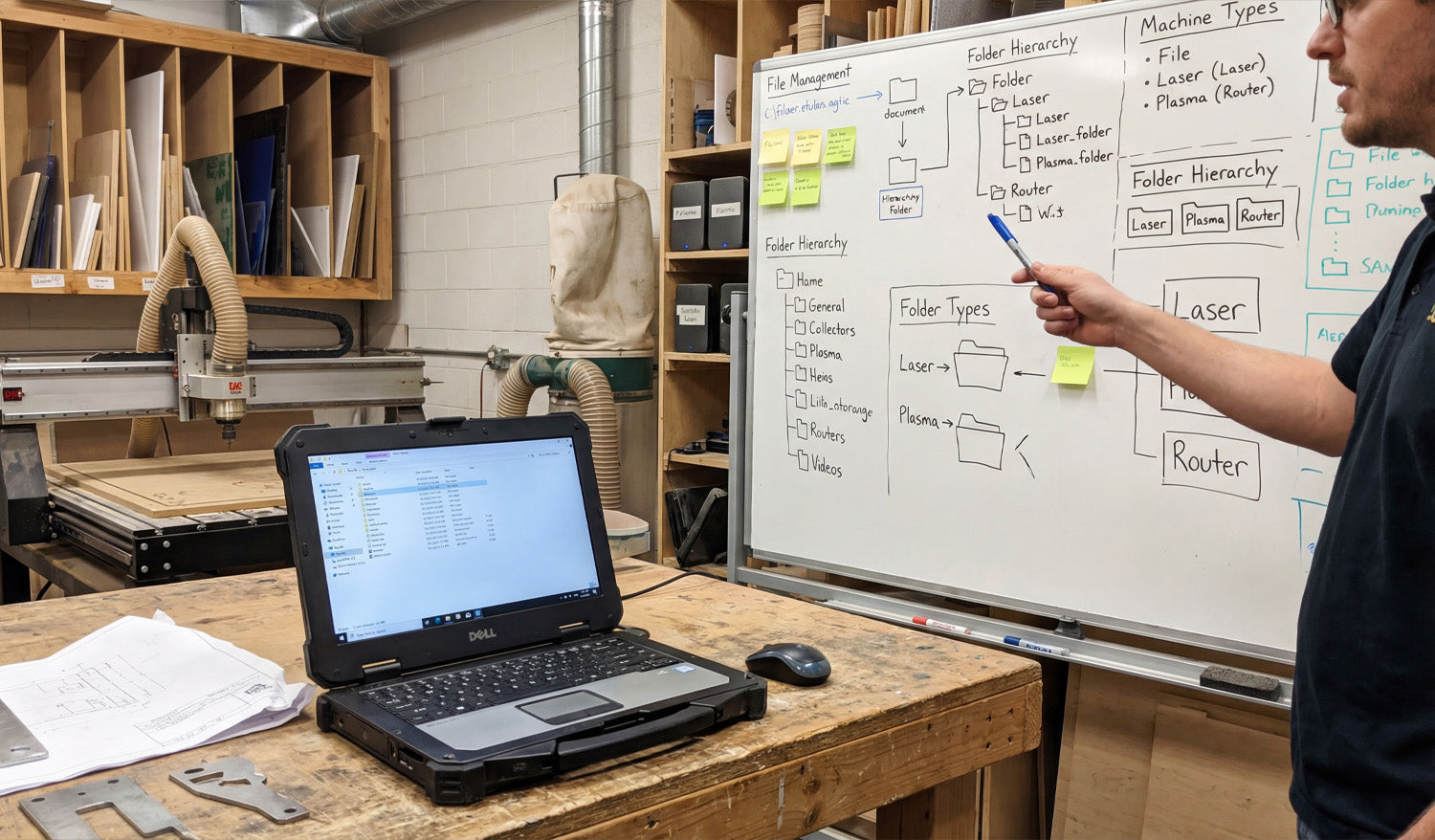
Managing multiple DXF files for large-scale CNC projects is all about control: clear structure, consistent naming, and a simple system that keeps designers, programmers, and machine operators working from the same, correct files every time. Why Large-Scale CNC Projects Need a DXF System (Not Just Folders) Cutting one small sign is easy. Cutting hundreds of parts for a big install, production run, or full product line is different. You may have: Dozens or hundreds of DXF files for a single project. Multiple machines (laser, plasma, router) using different versions of the same part. Revisions, client changes, and engineering updates happening mid-job. Without a system, DXF files get duplicated, lost, or mixed up. A simple structure and workflow lets you scale up without chaos. 1. Organize DXF Files by Project First, Then by Machine For large jobs, think in terms of projects, not just part types. A solid starting structure looks like this: Projects Project_ABC_2025 00_Input (customer drawings, PDFs, photos) 10_CAD_Master (original CAD and vector files) 20_DXF_Production Laser Plasma Router 30_CAM (CAM project files and nesting layouts) 40_GCode (posted NC programs) 99_Docs (BOM, notes, approvals) This structure keeps everything for one project in one place, while still separating DXF files by machine type. 2. Use a Naming Convention That Scales When you have many DXF files, good names are more useful than good memory. A simple, scalable pattern might be: [ProjectCode]_[PartID]_[Material]_[Thickness]_[Process]_[Rev].dxf For example: ABC01_PanelA_steel_3mm_laser_R1.dxf ABC01_Bracket02_aluminum_5mm_plasma_R2.dxf Key points: ProjectCode: Links the part to a specific job or customer. PartID: Matches your drawing number or BOM code. Material & thickness: Makes it easy to pick the right file for the right sheet. Process: Laser, plasma, router, waterjet, etc. Revision: R1, R2, R3… so you always know which is latest. 3. Separate Master Design Files from Production DXF Files In large projects, master design files and production DXF files should never be the same thing. Master files: CAD, AI, SVG, or parametric models with full design detail. Production DXF: Clean 2D profiles ready to import into CAM or the controller. Keep master files in 10_CAD_Master and export only the geometry you actually need into 20_DXF_Production. This way: Design changes are made in the master, not hacked on the shop floor. Production DXFs remain simple, predictable, and easy to regenerate. 4. Link DXF Files to Your Bill of Materials (BOM) For large-scale CNC projects, your DXF library should match your BOM. Every physical part on the BOM should have a clear DXF link. Add a column in your BOM for DXF filename. Use the same PartID in both the BOM and the DXF name. Mark which parts are cut, bent, purchased, or assembled. When production asks, “Which DXF do we cut for Part 27?”, the BOM should answer that without hunting through folders. 5. Define Clear Revision Rules for DXF Changes On big jobs, revisions are guaranteed—client requests, design improvements, or fit issues. Without rules, old DXFs keep resurfacing. Use R1, R2, R3 in filenames and keep old versions in a subfolder like _Archive. Only one version per part should live in the main DXF_Production folder. Update the BOM and any printed drawings when a revision goes live. Communicate changes to operators so they know old NC code may no longer be valid. A simple revision system prevents the “wrong version” from being cut when it matters most. 6. Group DXF Files by Material and Thickness for Nesting Large-scale projects usually involve long nesting sessions. It is painful if you have to manually pick through every DXF just to find parts for 3 mm steel. Inside DXF_Production, use folders such as: Laser Steel_3mm Steel_6mm Aluminum_4mm Only place DXFs that are actually cut from that material/thickness into those folders. Now, when you nest Steel_3mm, you are only looking at relevant DXFs for that sheet, not the entire project. 7. Use Simple Documentation Inside the Project Folder A single text file can save hours of confusion on large jobs. Add a small README.txt or Notes.txt in each project: Describe material lists and which folders hold which parts. List any special cutting instructions (micro tabs, etching, priority parts). Note the current revision status (for example, “All parts at R2 except Bracket03 at R3”). This is especially helpful when multiple people are sharing the same DXF library across shifts or departments. 8. Automate Repetitive Work Where Possible Large-scale DXF management often has repetitive tasks that can be partly automated: Batch renaming: Apply your naming convention to many files at once. Folder sorting: Move DXFs into material-thickness folders based on patterns in the file names. Preview generation: Export small PNG/JPG previews from your CAD or CAM system to quickly identify parts. Even simple automation can remove hours of manual sorting and naming when you handle dozens or hundreds of DXF files per project. 9. Centralize Storage and Control Access For large jobs, you cannot afford “secret” copies of DXFs living on random desktops and USB drives. Store all project folders on a central server, NAS, or cloud-synced location. Give designers and engineers edit access to master and DXF folders. Give machine operators read-only access to DXF and G-code folders. Avoid copying DXFs manually to local machines unless necessary; always keep the “source of truth” centralized. This minimizes version drift and ensures everyone works from the same set of approved DXFs. 10. Run a Pre-Production Audit of Your DXF Set Before you start cutting full sheets for a large project, do a quick audit of your DXF collection: Verify that every BOM part has a matching DXF. Check that material and thickness in the filenames match what you plan to load. Open a random sample of DXFs to confirm closed profiles, no duplicates, and correct scale. Confirm that revisions in the DXF names match the BOM and printed drawings. A short audit up front is cheaper than discovering a missing or outdated DXF halfway through a big run. Quick Checklist for Managing Multiple DXF Files Before you call a large project “ready,” check that: ✔ DXF files are organized by project, then by machine and material. ✔ A clear, consistent naming convention is used across all parts. ✔ Master design files are separated from production DXFs. ✔ Each BOM line item is linked to a specific DXF filename. ✔ Revisions and archives are handled in a predictable way. ✔ Material/thickness folders are ready for nesting. ✔ Project notes explain special instructions and current revision status. ✔ Storage is centralized, with controlled access for different roles. Conclusion Managing multiple DXF files for large-scale CNC projects does not require complex software—just a clear structure, consistent naming, and simple habits that everyone on the team follows. When your DXF library is organized by project, machine, material, and revision, you can scale up jobs, share work between operators, and run long production batches with far fewer mistakes, delays, and surprises on the shop floor.
How to Create 3D CNC Models from DXF Files
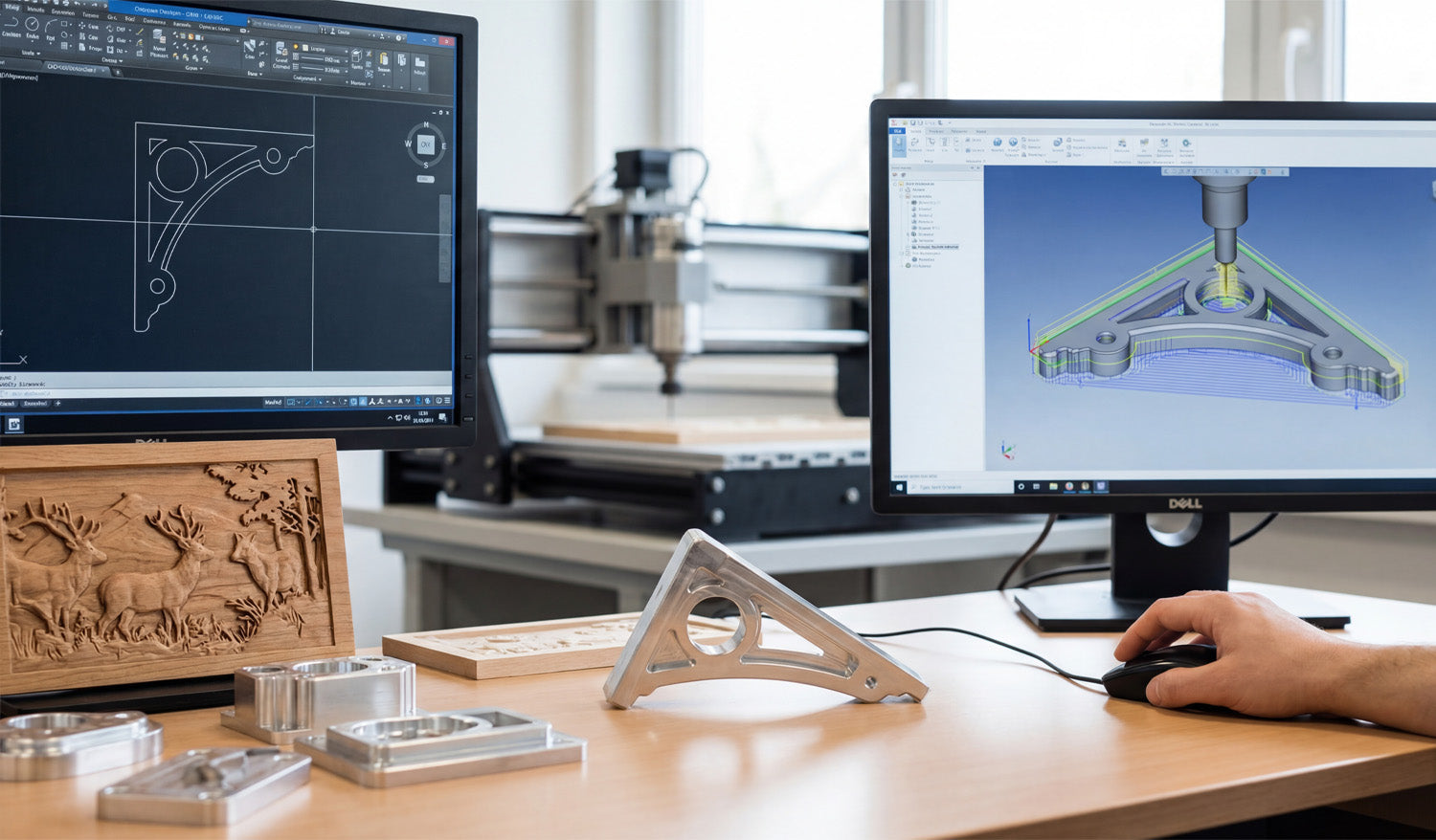
Creating 3D CNC models from DXF files is a smart way to turn flat drawings into real-world parts, fixtures, molds, or carved surfaces that your router or mill can machine with confidence. How DXF Fits Into a 3D CNC Workflow DXF files are usually 2D: profiles, outlines, and flat shapes. But those same profiles are exactly what 3D CAD and CAM software need as a starting point for solid models and 3D toolpaths. DXF = 2D geometry: Contours, centerlines, holes, and part outlines. 3D model = volume: Thickness, pockets, slopes, fillets, and complex surfaces. CNC = motion: Toolpaths that follow the 3D model and generate real parts. The goal is to move smoothly from “good 2D DXF” to “clean 3D model” to “reliable 3D toolpaths.” Step 1: Clean Up the DXF Before Going 3D A messy DXF becomes an even messier 3D model. Start by fixing the basics while you are still in 2D. Confirm units and scale: Make sure the DXF is in mm or inches and that a known dimension matches real size. Close profiles: Outer outlines and inner cutouts should be true closed loops with no tiny gaps. Remove duplicates: Delete overlapping lines, arcs, and stacked geometry. Clean stray elements: Get rid of points, construction lines, and tiny scraps you do not need. Separate layers: Put different shapes (holes, outlines, centerlines) on logical layers if they are not already organized. Think of this step as “detail prep.” A few minutes of cleanup now saves hours of frustration later in 3D. Step 2: Import the DXF into 3D CAD as Sketches Most 3D CAD systems let you import DXF files directly into a sketch on a plane (usually the XY plane). Create or open a 3D CAD project. Start a new sketch on the plane where you want the part to sit. Import the DXF into that sketch instead of floating it somewhere in space. Lock the imported geometry to your origin or a reference point so your model has a clear zero. After import, run CAD tools like Trim, Extend, and Constraints to make sure the sketch is watertight and easy to extrude. Step 3: Turn 2D Profiles into 3D Features Once the DXF is a clean sketch, you can start turning lines into volume. Extrude for Flat Parts and Plates Select the closed outer profile from the DXF sketch. Use an Extrude command to give the shape thickness (for example, 10 mm or 1/4"). Cut internal profiles (holes, slots, pockets) by extruding them as “cut” operations through the solid. Revolve for Round Parts If the DXF includes half-profiles of round parts (flanges, rings, pulleys), identify the centerline. Use a Revolve operation around that axis to create full 3D bodies. Loft and Sweep for Complex Shapes Use multiple DXF sections at different heights and connect them with a Loft to create tapered or organic forms. Use a Sweep to extrude a DXF profile along a curve, for handles, rails, or decorative edges. With just extrude, revolve, loft, and sweep, most 3D CNC-ready shapes are already possible from a basic DXF. Step 4: Add Machining-Friendly Details in 3D A machinable 3D model is more than an extruded plate. Add features that reflect how cutting tools actually behave. Fillets and chamfers: Smooth sharp edges for strength, aesthetics, or better tool access. Pockets and steps: Model pockets with true depths and bottom radii to match your tools. Bosses and pads: Add raised areas where bolts, bearings, or clamps will sit. Tool access: Check that tools can reach all internal corners; add reliefs or larger radii if needed. Each tweak you make in 3D is one less surprise when you get to CAM and the real machine. Step 5: Build 3D Reliefs and Carvings from DXF Artwork For CNC routers and wood carving, DXF artwork is often the base for 3D relief models. Use DXF outlines as boundaries: Define the area where the relief will live (for example, a plaque border). Project DXF curves onto surfaces: Use them to guide sculpted areas, text, or logo regions. Convert layers into heights: Different DXF layers can represent different height zones in the 3D model. Combine with height maps if needed: Sculpt the main relief using a height map, then trim or frame it using DXF edges. The DXF provides clean edges and layout; the 3D tools provide depth, slope, and form for carving. Step 6: Move from 3D Model to CNC Toolpaths With a solid model in place, you are ready for CAM (Computer-Aided Manufacturing). The steps depend on how complex your part is. 2.5D Toolpaths from DXF-Based Models Use pocket operations for flat-bottom cavities and steps. Use contour/profile operations around outer and inner edges. Use drill cycles for holes defined in the DXF-derived model. Full 3D Toolpaths Use adaptive clearing / roughing to remove bulk material safely. Use parallel, scallop, or raster toolpaths to finish sloped or curved surfaces. Use pencil or contour finishing around tight internal features. Because the model came from a clean DXF, your toolpaths follow geometry that already makes sense in the real world. Step 7: Simulate, Check, and Correct Before Machining 3D CNC jobs are more expensive to get wrong. Simulation is your safety net. Simulate the full program to see how tools move and where material is removed. Check for collisions with clamps, fixtures, or neighboring features. Look for gouges and leftover material on critical surfaces. Verify that the stock size and zero point match how you will set up the machine. If something looks off, go back to the 3D model or DXF sketch, adjust, and regenerate toolpaths before cutting metal or wood. Step 8: Export CNC Code from the 3D-CAM Setup Once the simulation is clean, export the machine code from CAM. Choose the correct post-processor for your CNC controller (for example, Fanuc, Mach3, GRBL, or a machine-specific post). Save programs with clear names like partname_op1_roughing.nc and partname_op2_finish.nc. Keep the DXF, CAD, CAM project, and final G-code together in a labeled project folder for future reuse. At this point, your 3D CNC model has fully evolved from a flat DXF drawing into a ready-to-run machining job. Common Mistakes When Turning DXF into 3D Models Watch for these easy-to-avoid problems: Wrong scale: Importing DXF in the wrong units and building a full 3D model at 10× size. Open loops: Leaving gaps in the DXF sketch, which block extrudes and create broken solids. Too much detail: Bringing every tiny decorative line into a 3D machining project that does not need it. No thought for tools: Designing sharp inside corners that a round cutter simply cannot reach. Skipping test cuts: Going straight from screen to production without cutting a sample. Quick Workflow Checklist: DXF to 3D CNC ✔ Clean and organize the DXF (units, closed profiles, no duplicates). ✔ Import as a sketch in 3D CAD and constrain it properly. ✔ Extrude, revolve, loft, or sweep to build a solid model. ✔ Add machining-friendly details: fillets, chamfers, pockets, access radii. ✔ Create CAM toolpaths from the 3D model (2.5D and 3D as needed). ✔ Simulate and verify stock, zero, and collisions. ✔ Post-process to CNC code and run test cuts. ✔ Save everything (DXF, CAD, CAM, G-code) for future jobs. Conclusion Creating 3D CNC models from DXF files is one of the most efficient ways to connect flat drawings with real machined parts. By cleaning the DXF, importing it as a solid foundation for your 3D model, and then driving CAM from that model, you get predictable toolpaths and parts that match the original design intent. Whether you are machining fixtures, plates, brackets, or carved panels, a DXF-driven 3D workflow lets you go from sketch to finished part with far less trial and error.
Using DXF Files for Custom CNC Fabrication Projects
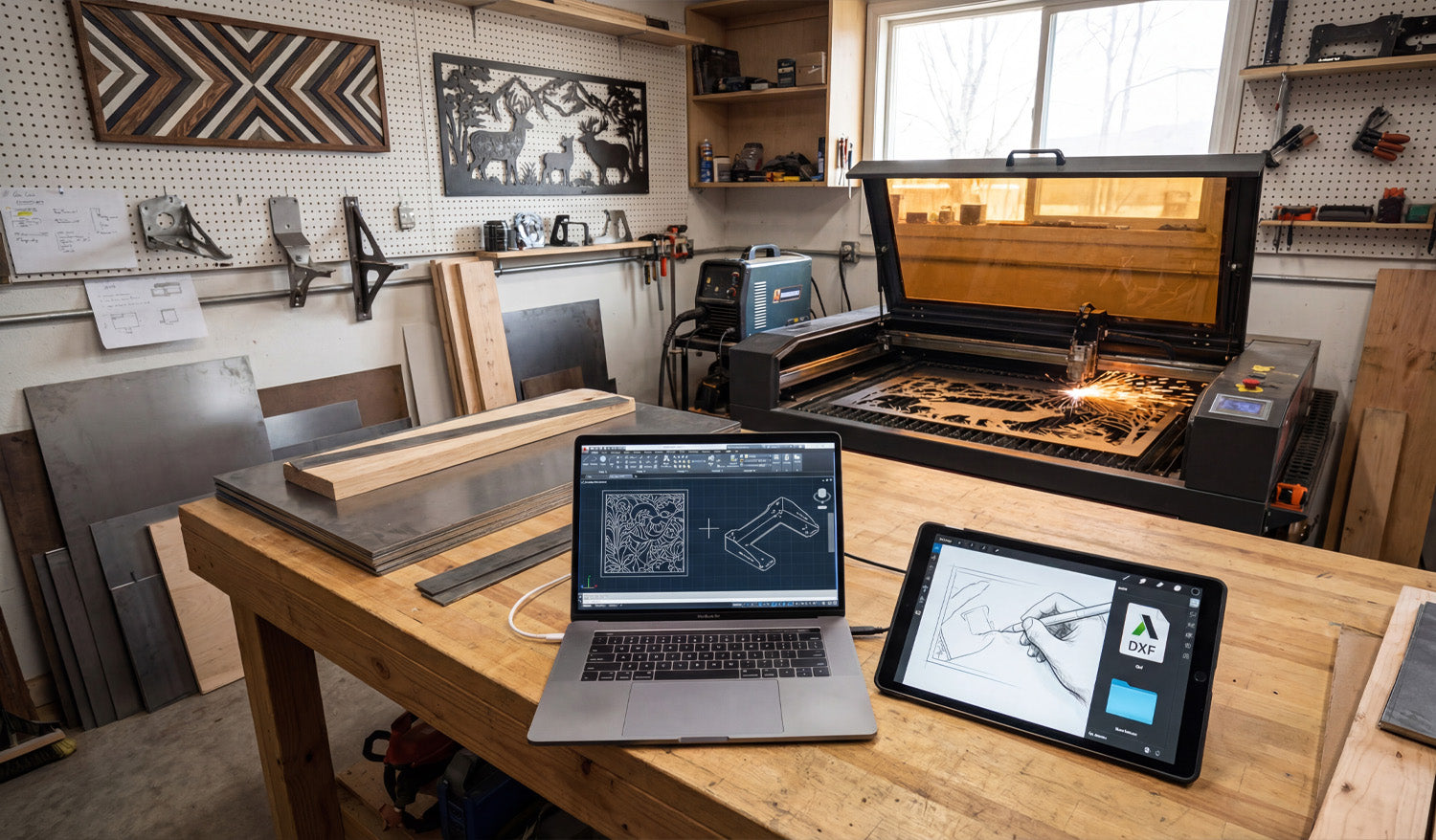
Using DXF files for custom CNC fabrication projects lets you move from rough ideas and quick sketches to accurate, repeatable parts that your laser, plasma, or router can cut without drama or guesswork. Why DXF Files Are Perfect for Custom CNC Work Custom fabrication is messy by nature: every project is a little different, dimensions change, clients change their minds, and you often work with one-offs or small batches. DXF files bring order to that chaos by acting as a stable, machine-ready language between design and cutting. Vendor-neutral: DXF is supported by almost every CAD, CAM, and CNC controller. Exact geometry: Lines, arcs, and curves are stored as precise vectors, not fuzzy pixels. Easy to revise: You can tweak a few dimensions, re-export, and be cutting again in minutes. For a shop that lives on custom jobs—signs, brackets, panels, fixtures, architectural parts—DXF becomes the backbone of your workflow. From Idea to DXF: Building a Custom CNC Workflow Most custom CNC projects follow a similar path, even if the details change from job to job: Capture the concept: A sketch, email, photo, sample part, or customer drawing. Translate into CAD or vector software: Create clean 2D geometry that reflects what must be cut. Export as DXF: Save a clean, simplified version for CAM and the CNC machine. Generate toolpaths: In CAM software, turn DXF profiles into real feed rates, pierces, and depths. Test cut and refine: Make small adjustments to fit, kerf, or aesthetics based on real parts. The DXF file is the bridge in the middle of this process—stable enough to feed the machine, flexible enough to change quickly when the job evolves. Using DXF Files to Collaborate with Clients Custom jobs often start with incomplete information. A client might send a rough drawing, a screenshot, or a picture of something they liked. DXF files help you turn that into something both sides can agree on. Share approval drawings: Send a DXF or a PDF exported from your DXF so the client can review shapes and dimensions. Capture revisions clearly: Update the DXF when the client asks for changes and keep version history (v1, v2, v3). Avoid miscommunication: Exact geometry and dimensioning in DXF remove a lot of “I thought it would be bigger” problems. Once the client signs off on the DXF-based drawing, you are not guessing—you are cutting exactly what was approved. Turning Standard Designs into Custom Parts with DXF One big advantage of working with DXF files is how easily you can customize existing designs without starting from zero every time. Adjust size: Scale panels, signs, and decorative pieces while maintaining proportions and cut-ready geometry. Modify features: Add holes, slots, or mounting brackets to fit a specific project. Personalize artwork: Swap names, logos, or monograms in a sign or wall-art template. By building a library of reusable DXF templates and then customizing them per project, you keep design time low and still deliver a “custom” experience to every customer. Using Layers in DXF for Fabrication Details Custom fabrication often includes more than just cutting. You may need bend lines, weld locations, or marking details on the same part. DXF layers are perfect for this. CUT_OUTSIDE: Final outer profiles of the part. CUT_INSIDE: Holes, slots, and internal cutouts. MARK or ENGRAVE: Text, logos, part numbers, or layout marks. BEND_LINES: Lightly etched lines indicating where to bend in the press brake. REFERENCE: Centerlines, datums, construction geometry that will never be cut. In CAM, you can map each layer to a different operation (full cut, light etch, ignore) without redrawing anything, which is ideal for complex custom parts. DXF Files Across Different CNC Processes in One Shop Many fabrication shops run more than one type of CNC machine. DXF files help you feed all of them from the same core geometry. Laser or plasma: Cut flat profiles for brackets, panels, and plates. CNC router: Cut plywood, MDF, plastics, and composite panels for furniture, signs, or fixtures. Water-jet: Cut thicker or heat-sensitive materials from the same DXF outlines. You can maintain a single “master DXF” for the profile and create different CAM setups (tools, kerf, feeds) per machine or material as needed. Designing Custom Parts in DXF with Real-World Constraints Custom fabrication is not just about shape; it is about fit and function in the real world. DXF files let you design with those constraints built in. Account for kerf: Draw tabs, slots, and joint details with expected kerf and clearance in mind. Respect minimum feature sizes: Avoid thin webs or micro details that will fail on your chosen process. Align with hardware: Use bolt patterns, hole sizes, and slot shapes that match standard fasteners. When you build these rules into your DXF designs, your “custom” parts still feel standardized and predictable on the machine. Managing DXF Libraries for Custom Fabrication Over time, your custom work becomes a catalog of proven DXF files you can reuse and adapt. Organize by category: Signs, brackets, gussets, fixtures, architectural, art panels, etc. Store master and production versions separately: Editable source vs. clean cut-ready DXF. Tag files with notes: Material used, ideal thickness, and any special cutting instructions. This library turns past projects into future shortcuts: when a new customer asks for something similar, you start from a proven DXF instead of a blank screen. Common Pitfalls to Avoid in Custom DXF Projects Custom projects can go sideways fast if the DXF is not prepared carefully. Watch out for: Open contours: Gaps in profiles that cause incomplete cuts. Duplicate lines: Overlapping geometry that makes the machine cut the same path twice. Hidden tiny shapes: Tiny islands or specks from tracing that add time and no value. Unclear layers: Everything on one layer, making it hard to separate cutting and marking operations. A quick pre-flight check of the DXF before CAM—especially on custom jobs—saves time, material, and customer frustration. Real-World Example: Custom Bracket for a One-Off Build Imagine a customer needs a special bracket to mount a new piece of equipment on an older frame. You measure the existing mounting points and sketch the bracket concept. You create a 2D profile in CAD, then export a DXF with slotted holes for adjustment. You run a quick test cut, check fit, and tweak slot length or hole diameter if needed. Once the bracket fits perfectly, you save that DXF in your library for future retrofits. From then on, what started as a one-off becomes a repeatable product in your shop—all driven by a clean DXF file. Conclusion Using DXF files for custom CNC fabrication projects turns loose ideas into cut-ready geometry that your machines understand. With DXF, you can collaborate clearly with clients, reuse proven designs, manage multi-step fabrication details on layers, and feed different machines from the same core profiles. For any shop that thrives on custom work, DXF is not just another file format—it is the foundation of a faster, more reliable, and more profitable CNC workflow.
Tips for Organizing and Storing Your DXF Files for CNC Machines
Well-organized DXF files can make your CNC shop feel faster and calmer. Instead of hunting through random folders, you always know where each design lives, which version is current, and which file is ready for which machine. Why DXF Organization Matters More Than You Think DXF files are the language your CNC machines speak. When they are scattered across hard drives with names like new_11_final.dxf, you waste time on: Searching for the “right” version before every job. Accidentally cutting outdated or untested designs. Duplicating work because you cannot find past projects. A simple folder structure, clear file names, and a basic backup plan can remove most of this chaos and let you focus on cutting parts, not chasing files. 1. Start with a Simple, Repeatable Folder Structure You do not need a complicated system—just one you can actually stick to. A good starting point for DXF files might look like this: DXF Library Laser Plasma Router Mill Inside each machine folder, group designs by use or style: Laser → Signs, Wall Art, Logos Plasma → Brackets, Yard Art, Fire Pits Router → Furniture Parts, Jigs, Inlays Keep it logical and consistent. The test is simple: can someone else on your team find a file in under 30 seconds? 2. Separate “Master” Files from “Production” Files One of the best habits you can build is treating design and production files differently. Master files: Your fully editable originals (CAD, AI, SVG). These may contain construction lines, notes, and extra detail. Production DXF: Clean, simplified files ready for import into CAM or your CNC controller. Example folder layout: DXF Library Master Production This approach lets you edit and experiment without breaking the file that the shop floor uses every day. 3. Use Descriptive, Machine-Friendly File Names File names are tiny labels that can carry a lot of useful information. A good DXF name answers at least three questions: What is it? What size is it? What material or thickness is it for? For example: wolf_wall_art_600mm_steel3mm_v2.dxf bracket_L_100x50_aluminum5mm_v1.dxf You can also add the target machine when it matters: panel_pattern_large_laser_only_v3.dxf bracket_set_router_plywood18mm_v2.dxf Clear names reduce questions and miscuts, especially when you run multiple machines and materials. 4. Version Your DXF Files Before Things Get Messy Designs evolve. A joint is too tight, a slot is too loose, or a logo changes. If you do not manage versions, your DXF folder slowly becomes a puzzle. Add a simple version tag: v1, v2, v3 at the end of the name. Only mark one file as the current production version (for example, in a text note or by moving old versions to an Archive subfolder). When a change is made because of a real test cut, always bump the version number. Small shops often skip versioning until they regret it. Start early while your library is still manageable. 5. Organize by Machine, Material, and Thickness If you cut the same design on different machines or materials, give each combination its own home. By machine: Keep separate folders for Laser, Plasma, Router, and Mill. By material: Inside each, use folders for Steel, Aluminum, Stainless, Plywood, Acrylic, etc. By thickness: For example, Steel_3mm, Steel_6mm, Birch_12mm. Why? Because kerf, fit, and toolpaths often change with thickness. Keeping these variants separated avoids mixing “steel 3 mm” cut files with “steel 10 mm” jobs. 6. Keep Reference Material and CAM Files Nearby DXF files rarely live alone. They are usually part of a small “bundle” for each project. DXF folder: Clean geometry ready for CAM. CAM folder: Toolpath files or project files for your CAM software. Previews: JPG or PNG images that show what the final part should look like. Notes: A text file with best-known feeds, speeds, or power settings. A simple structure like this turns each job into a self-contained package you can pick up months later with minimal guesswork. 7. Use Cloud or NAS Storage for Shared Access If more than one person is using your DXF library, local storage on a single PC quickly becomes a bottleneck. Use a shared network drive or NAS so all shop computers access the same “truth.” Consider a cloud-synced folder for backup and remote access. Limit who can edit “Master” folders; give operators read-only access where appropriate. This reduces the risk of “secret” copies living on USB sticks and laptop desktops where they are never updated or backed up. 8. Back Up Your DXF Library Like It Is Business-Critical (Because It Is) Your DXF files represent hours or years of work. Treat them like an asset, not an afterthought. Set up automatic daily or weekly backups of your DXF and CAM folders. Keep at least one backup off-site or in the cloud in case of fire, theft, or hardware failure. Test your backup by restoring a sample project occasionally. A good backup policy means a failed hard drive is an inconvenience, not a disaster. 9. Use a Simple Index or Catalog for Large Libraries Once your DXF collection grows beyond a few hundred designs, a basic catalog makes life easier. Create a spreadsheet or simple database listing: File name Category (animals, signs, brackets, fixtures, etc.) Target machine and material Notes about sizes or popular variations Add a column for “approved for production” so you know which designs have been test cut. This does not have to be fancy. Even a basic index helps you remember what you already have before you redraw the same idea again. 10. Standardize Your Workflow for New DXF Files Finally, make sure every new file enters your system the same way. For example: Design or edit in CAD/vector software. Save the editable master in the Master area. Export a clean DXF to the correct Production folder (Laser/Plasma/Router/Mill). Rename according to your file-naming rules. Run a test cut, then update the version number if you make adjustments. When this process is documented and followed by everyone, your DXF library stays organized automatically instead of slipping into chaos over time. Conclusion Organizing and storing DXF files for CNC machines is not about perfection; it is about consistency. A clear folder structure, descriptive file names, simple version control, shared storage, and regular backups turn your DXF collection into a powerful, reliable asset. With a little discipline now, you will spend far less time searching for files and far more time running profitable CNC jobs.
Top Tips for CNC Design Success: Mastering DXF Files
Mastering DXF files is the fastest way to improve your CNC design success, cut cleaner parts, and move from idea to finished product with less stress, less scrap, and more profit. Why DXF Files Are So Important for CNC Design DXF (Drawing Exchange Format) is the universal language of 2D CNC work. Whether you run a laser, plasma, router, or milling machine, DXF files act as the bridge between your design software and your CNC controller. When your DXF files are clean, organized, and designed with the machine in mind, you get: Smoother toolpaths and better edge quality. Shorter setup and programming time. More predictable results from job to job. Fewer surprises on the machine and less rework. Tip 1: Start with a Clear Design Intent Before you draw a single line, define what you are trying to achieve with the part or artwork. Function: Is it decorative wall art, a structural bracket, a sign, a fixture, or a part for assembly? Machine type: Laser, plasma, router, or mill—each has different strengths and limits. Material: Steel, stainless, aluminum, MDF, plywood, acrylic, or something else? Finish: Will the part be painted, powder-coated, polished, or left raw? A clear design intent helps you make smarter choices about feature sizes, text thickness, joint types, and overall detail level in your DXF file. Tip 2: Work in the Right Units from the Start Unit issues are one of the most common hidden problems in CNC design. Get this right at the beginning. Choose millimeters or inches as your standard and stick to it in both CAD and CAM. Set your design template to the correct units so every new DXF starts correctly. Include at least one known dimension (for example, a 100 mm or 4 inch reference) to verify scale after import. Good DXF files open at the correct size with no guessing, making life easier for whoever runs the machine. Tip 3: Keep Geometry Clean, Closed, and Connected Clean geometry is the foundation of CNC success. Dirty DXF files cause broken cuts, strange toolpaths, and wasted time. Close all profiles: Outer shapes and inner cutouts should be fully closed loops with no gaps. Remove duplicate lines: Delete overlapping paths so the machine does not cut the same line twice. Eliminate stray elements: Get rid of tiny segments, points, and construction marks that are not part of the final cut. Use polylines: Combine separate segments into continuous polylines where possible for smoother motion. Spending a few minutes cleaning your DXF before CAM can save you hours of troubleshooting on the CNC table. Tip 4: Control Node Count for Smooth CNC Motion Too many nodes (control points) make your machine stop and start constantly, leading to rough edges and slower cuts. Use simplify or optimize curve commands to reduce node density on curves. Convert “stair-stepped” curves or auto-traced outlines into smooth arcs or splines. Target areas with heavy detail: tight corners, curves from traced images, and decorative textures. Your goal is to keep the visual shape the same but let the CNC machine follow it with fewer, smoother moves. Tip 5: Design with Your CNC Machine in Mind Each type of CNC machine has its own design rules. Mastering DXF means respecting those limits from the start. Laser: Can handle fine detail, but very thin bridges in thin material may burn away. Plasma: Has a wider kerf; avoid tiny holes and micro text, and use thicker bridges. Router: Uses round bits; inside corners must have a radius or dogbone/T-bone relief. Milling: Needs tool access; deep pockets and narrow slots must match your tool length and diameter. A DXF that is “machine-aware” is much easier to run at speed without breaking tools or losing detail. Tip 6: Use Layers to Separate Operations Layers turn a messy drawing into a structured CNC plan. They help CNC operators see exactly what each line is meant to do. Create layers like CUT_OUTSIDE, CUT_INSIDE, ENGRAVE, SCORE, and HOLES. Place through-cuts on one layer and engraving or marking on another. Use a reference layer for centerlines, dimensions, and datums that should never be cut. Assign distinct colors to layers if your CAM or controller uses color mapping. When the DXF reaches CAM, you can map entire layers to speed, power, and depth settings with just a few clicks. Tip 7: Respect Kerf, Minimum Feature Size, and Material Strength Designing without thinking about kerf and material behavior is a fast way to create beautiful but unusable parts. Know your kerf width (cut width) for each process and material. Make sure bridges, webs, and thin features are wider than the kerf and strong enough for handling. Leave enough material around holes and slots so parts do not warp or break. For joints, design slots and tabs with realistic tolerances so they fit after kerf compensation. Good DXF design is about balancing visual detail with what the material and machine can reliably produce. Tip 8: Make Text and Logos CNC-Friendly Text and logos often cause problems in CNC design because they start as fonts or bitmaps rather than clean vectors. Convert text to curves/outlines before exporting to DXF so it does not depend on missing fonts. Use stencil-style lettering for cut-out text so inner islands (A, O, P, R, D, etc.) do not fall out. Keep stroke widths thick enough for your material and machine process. For logos, clean up traced artwork by removing unnecessary nodes and small, fragile shapes. Well-prepared text and logos give you clear engravings and cut-outs that hold their shape and stay readable. Tip 9: Build and Organize a Reusable DXF Library One of the biggest “pro moves” in CNC design is building your own DXF library instead of starting from zero every time. Save proven parts—tabs, brackets, gussets, hinges, logos—as separate DXF files or blocks. Organize them by category: Structural, Decorative, Fixtures, Logos, Panels, and so on. Use clear naming: include size, material, and version where it makes sense (for example, hinge_80mm_steel_v2.dxf). Keep notes or a text file with best-known settings and common uses for each design. Over time, this library becomes a powerful asset you can reuse across projects, saving huge amounts of design and CAM time. Tip 10: Test on Scrap and Refine Your DXF Designs No matter how good your DXF looks on screen, the real proof is on the machine. Cut small samples on scrap material before committing to full sheets or production runs. Check fit, edge quality, and strength of joints, bridges, and small features. Adjust the DXF where needed: widen slots, thicken weak areas, simplify details that do not cut well. Save improved versions of your DXFs with new version numbers so you always know which one works best. Think of each test as an investment in a stronger, more reliable design that will serve you many times in the future. Tip 11: Avoid the Most Common DXF Mistakes To master DXF files for CNC, stay away from these classic pitfalls: Designing “for the screen” only: It looks great in CAD, but ignores kerf, material thickness, and machine limits. Leaving messy geometry: Open paths, duplicates, and stray lines that cause unexpected cuts. Ignoring layers: Putting everything on “Layer 0” and making CAM setup slow and confusing. Using raw auto-traced images: Outlines full of noise and micro segments that kill cutting speed. No unit or scale check: Importing a part and discovering it is 10× too small or too large after programming. Tip 12: Standardize Your DXF Workflow Finally, turn your best practices into a repeatable process so every new design starts strong. Create a DXF template file with layers, colors, and units preconfigured. Use a short checklist before export: closed paths, no duplicates, correct scale, simple curves, proper layers. Document your internal standards for bridge width, minimum feature size, and text height per material. Train everyone on your team to follow the same steps so files are consistent regardless of who designed them. This kind of standardization is what separates hobby-level work from a professional CNC design and manufacturing workflow. Conclusion Top CNC design success is not about having the most powerful machine—it is about feeding that machine well-built DXF files. By starting with clear design intent, keeping geometry clean, respecting your machine and material limits, using layers wisely, and building a reusable DXF library, you turn each drawing into a reliable CNC blueprint. Mastering DXF files is how you move from guesswork and rework to predictable, profitable CNC projects on every job.
The Future of CNC Cutting: What’s Next for DXF Files?
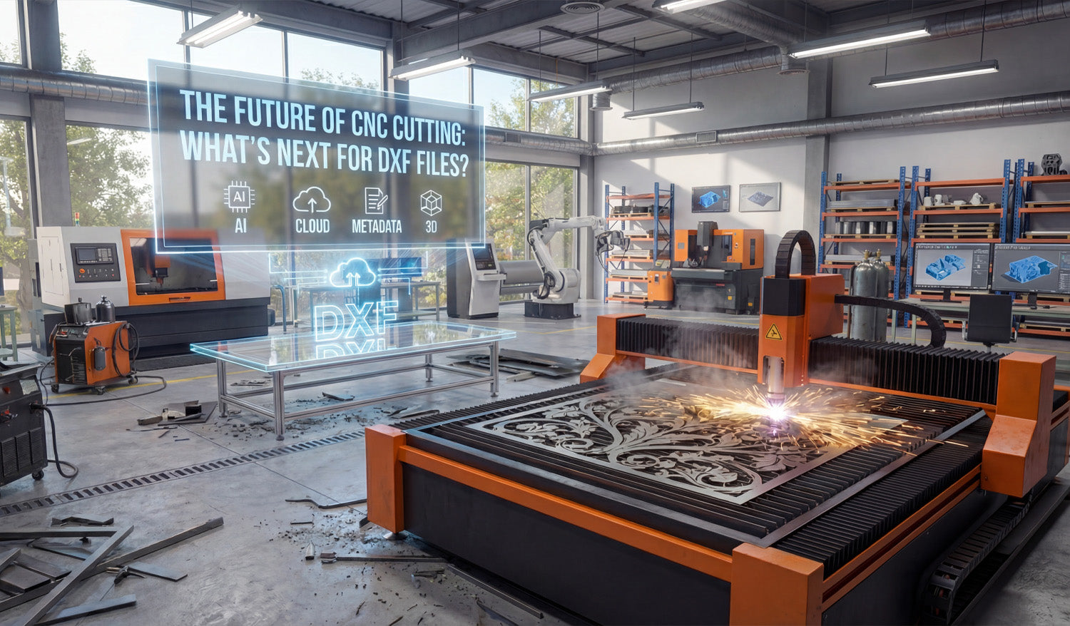
The future of CNC cutting will still include DXF files at the core, but they will be smarter, cleaner, and more connected to cloud, AI, and automation workflows. DXF Is Not Going Away Any Time Soon Despite new formats and 3D workflows, DXF remains one of the most trusted ways to move 2D geometry between CAD, CAM, and CNC machines. Almost every laser, plasma, router, and water-jet system can read DXF directly or through a simple import step. Because so many shops, design libraries, and CAM tools rely on DXF, it is far more likely to evolve than to disappear. The future of CNC cutting will probably look like “DXF plus extra intelligence,” not “no DXF at all.” Trend 1: Smarter, AI-Assisted DXF Cleanup Today, a lot of time is spent cleaning DXF files by hand: closing gaps, removing duplicates, reducing nodes, and fixing small geometry errors. In the future, more of this work will be automated. Automatic repair: Tools will detect open paths, overlapping lines, and bad splines and fix them in one click. AI-based simplification: Systems will recognize “visual detail” vs “noise” and remove extra nodes without changing how the design looks. Process-aware editing: Software will optimize DXF files differently for laser, plasma, router, or milling based on your chosen machine. This means you will spend less time cleaning files and more time actually cutting parts or building products. Trend 2: DXF Files with Richer Metadata Classic DXF files mainly store geometry. The future will likely add more context directly around that geometry. Material hints: Recommended materials and thickness ranges stored as metadata. Preferred settings: Suggested speeds, powers, or feeds and speeds linked to the design. Manufacturing notes: Information about minimum bridge sizes, best nesting orientation, or optional engraving layers. Instead of a “dumb” drawing, DXF files will act more like mini CNC recipes that help you get to a good cut faster—even if you are importing the design into a new CAM system. Trend 3: Cloud-Based DXF Libraries and Collaboration More CNC shops are moving their design libraries to the cloud. That changes how DXF files are stored, shared, and updated. Central libraries: Teams will access the same DXF collections from any machine or location. Version tracking: Changes to a DXF file—slot sizes, hole patterns, logo updates—will be tracked like code changes in software projects. Instant distribution: When a design is improved or fixed, every operator gets the updated DXF immediately. For digital design shops, this also means customers can browse online collections, purchase commercial bundles, and download cut-ready DXF files directly into their own CNC workflow. Trend 4: Tighter Integration with 3D Workflows Even though DXF is a 2D format, it will remain an important bridge between 3D models and real CNC cutting. Automated profile extraction: CAM tools will pull 2D views and section profiles from 3D models and export them as DXF for flat cutting. Sheet-metal workflows: Unfolded flat patterns (developed blanks) will be saved as DXF for cutting before bending and forming. Fixture plates and templates: Complex 3D fixtures will use DXF-based plates and drilling patterns as part of the overall setup. In many shops, the future will look like: model in 3D, generate critical 2D profiles as DXF, then cut them on laser, plasma, or router tables as part of a bigger, mixed process. Trend 5: DXF Files Tuned for Automation and Lights-Out Production As more CNC shops push toward automation and lights-out cutting, DXF files will need to be more predictable and standardized. Standardized layers: Layer naming and color conventions will be aligned with automated CAM templates. Ready-to-nest shapes: DXF profiles will be designed for dense nesting and minimal scrap right from the start. Error-free geometry: Automated pipelines will reject DXF files that do not meet certain quality rules (closed loops, no duplicates, valid scale). Clean, standardized DXF designs will flow from online libraries into nesting software, into the machine queue, and onto the table with very little human intervention. Trend 6: Hybrid Vector–Raster Workflows for Engraving Laser engraving is already moving toward hybrid workflows where vector and raster data work together. DXF will stay important on the vector side. Mixed jobs: DXF outlines for cutting and scoring, combined with bitmap layers for photo engraving. Procedural fills: Vector borders and regions defined in DXF, filled with hatch patterns or shading controlled at the CAM stage. Parametric personalization: Names, numbers, and logos updated automatically inside a DXF-based template for batch engraving jobs. In this future, DXF files define the “structure” of the design, while engraving styles and textures are applied dynamically at the machine level. Trend 7: More DXF Content, Fewer “Random” Designs The CNC world already has thousands of DXF files online, but many are low quality or not truly cut-ready. The next wave will focus on curated, well-tested content. Production-grade bundles: Large DXF libraries optimized for real machines and real materials. Proven designs: Files that have been cut, refined, and documented with recommended settings. Category depth: Specialized sets for wildlife art, architectural panels, brackets, fire pits, yard art, and more. For CNC businesses, the value will shift from “any DXF” to “the right DXF”—files that cut cleanly, nest well, and turn into products that customers actually want to buy. Trend 8: DXF as Part of a Full Digital Product Ecosystem Finally, DXF files will increasingly be seen as part of a bigger digital product, not just a raw drawing. Multi-format packs: DXF bundled with SVG, AI, PDF, and high-resolution preview images. Documentation: Cut examples, photos of finished products, and notes on how to sell or display them. Licensing and tracking: Clear license terms and purchase records for shops that sell physical products made from the designs. This ecosystem perspective turns a single DXF file into a complete, reusable asset for makers, fabricators, and CNC businesses. What This Means for CNC Shops and Makers For most CNC users, the message is simple: DXF is here to stay, but it is becoming more powerful. Invest in clean, high-quality DXF libraries instead of random, untested files. Adopt consistent DXF standards for layers, naming, and quality checks in your own shop. Be ready to plug into cloud, AI, and automated CAM tools that will make your DXF workflow even faster. If you build good habits now—file organization, clean geometry, and reliable design sources—you will be ready for whatever the future of CNC cutting brings to DXF files and beyond.
How to Use Free DXF Files for Your CNC Projects
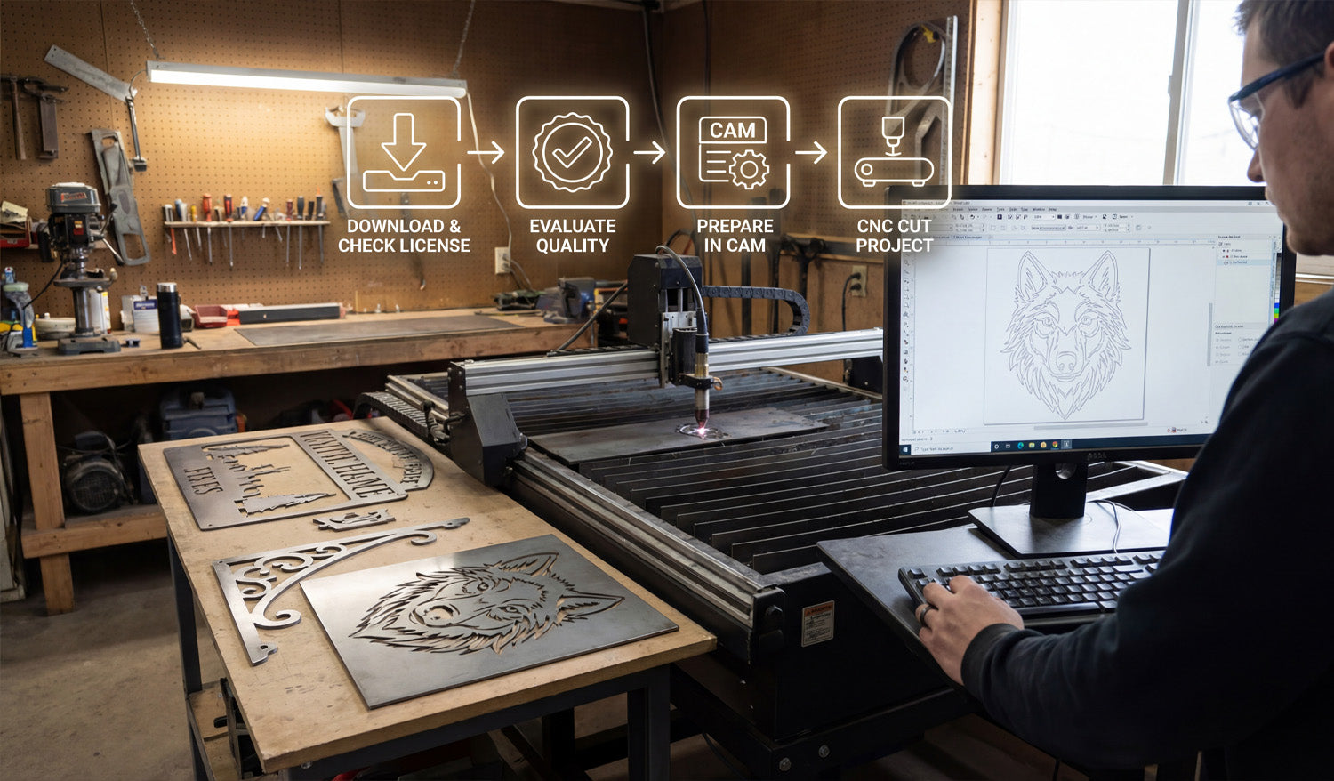
Free DXF files can help you test ideas, reduce design time, and launch new CNC projects faster—if you know how to find, check, and prepare them. What Are Free DXF Files? DXF (Drawing Exchange Format) files are 2D vector drawings made of lines, arcs, and curves. A “free DXF file” is simply a DXF design you can download at no cost from a website, forum, or community library. You can use these files as ready-made artwork, as a starting point to customize your own designs, or as practice material when you are learning how to run a CNC laser, plasma, router, or water-jet machine. Benefits of Using Free DXF Files in CNC Projects Free DXF files can be surprisingly powerful in your workshop if you use them the right way. Save design time: Skip the blank page and start from a design that is already drawn. Test your machine: Use free files to dial in speeds, power, kerf, and feeds on new materials. Prototype ideas: Try new product concepts without paying a designer or spending hours in CAD. Inspire new products: Study how good files are built and adapt layouts, proportions, and themes for your own designs. Learn the workflow: Practice importing, nesting, and cutting DXFs before you move to critical customer jobs. Where to Find Free DXF Files Safely You can find free DXF files in many places online, but quality and licensing vary a lot. Look for sources that: Focus specifically on CNC cutting and engraving (not just random clipart). Offer clear license information about personal and commercial use. Provide preview images so you can see what the final cut should look like. Have organized categories like animals, signs, panels, brackets, and so on. On your own site, you might maintain a dedicated section for free designs. For example, you can browse and download sample designs from a collection like Free DXF Files and test them on your laser, plasma, or router before investing in larger bundles. Always Check the License Before You Cut “Free” does not always mean “do anything you want.” Before you use a DXF file in a paid project or product line, read the license carefully. Personal use only: You can cut the design for yourself or as a gift, but not sell physical products made from it. Commercial use allowed: You can sell physical items made from the design (signs, wall art, brackets, etc.). No digital resale: In most cases you cannot resell, share, or repackage the DXF file itself as a digital product. Attribution requirements: Some licenses ask you to credit the designer or site. If the license is unclear, treat the file as personal-use only or choose a file from a source with clearly written terms. How to Evaluate the Quality of a Free DXF File Not every free DXF is cut-ready. Before you rely on a file, open it in your CAD or CAM software and do a quick quality check. Closed paths: Outer profiles and inner cutouts should be fully closed loops, not “almost closed” shapes with tiny gaps. No duplicate lines: Make sure there are no overlapping paths that could cause double cuts. Reasonable node count: Curves should be smooth with a sensible number of points, not thousands of tiny segments. Correct scale: Measure the design; it should import at a realistic size in mm or inches. Material-friendly detail: Thin bridges and tiny shapes should be big enough for your material thickness and kerf. If a file fails these tests, you can either clean it up or move on to a better DXF that saves you time instead of creating headaches. How to Prepare Free DXF Files for Your CNC Machine Even a good DXF file needs a little setup work before you cut it. Here is a simple workflow you can reuse: Import the DXF: Open the file in your CAD or CAM software. Confirm units and size: Measure a known feature and scale if needed so the part matches your target dimensions. Clean the geometry: Close open paths, delete duplicates, and remove stray points or tiny islands. Organize layers: Separate cut, engrave, and reference geometry into layers or colors if they are not already organized. Match detail to material: If the design is too detailed for your material or plasma kerf, simplify small features. Set toolpaths in CAM: Assign inside cuts, outside cuts, and engraving passes with proper speed, power, and kerf compensation. Run a test cut: Use scrap material to verify fit, edge quality, and overall look before running a full sheet or final product. Project Ideas Using Free DXF Files Free DXF files are perfect for learning, testing, and even launching simple product lines. Here are a few ideas: For Laser Cutters and Engravers Decorative wall art and panels. Custom keychains and ornaments. Nameplates, door signs, and small plaques. Engraved coasters, cutting boards, and gift items. For CNC Plasma Cutters Metal wall art and monograms. Fire pit panels and grills. Brackets, tabs, and gussets for fabrication. House number signs and yard art. For CNC Routers Wooden signs and 2.5D plaques. Simple furniture parts and brackets. Shelf supports, jigs, and fixtures. Inlay patterns and decorative panels. Organizing Your Free DXF Library As you download more free DXF files, a little organization will save you a lot of time later. Create folder groups like Laser, Plasma, and Router. Inside each, organize by category: Animals, Signs, Panels, Brackets, and so on. Use clear file names with type, size, and maybe material (for example, wolf_wall_art_600mm_steel.dxf). Keep notes on files you have already tested: best material, power, and speed settings. Over time, your “free DXF” folder can become a powerful design library that you reuse again and again. When to Move from Free DXF Files to Paid or Custom Designs Free DXF files are great, but they have limits—especially if you run a business. Originality: Popular free designs are used by many shops, so products may not feel unique. Depth of content: Free libraries are usually small compared to large commercial bundles. Support and consistency: Paid design sets are often more consistent in style, sizing, and cut quality. Once you know which styles sell or which categories your customers love, investing in high-quality DXF bundles or custom artwork can help you stand out and scale your CNC shop faster. Conclusion Free DXF files are a smart way to explore CNC projects, test new materials, and speed up your design process without extra cost. By choosing reputable sources, checking the license, cleaning the geometry, and organizing your downloads, you can turn “free files” into real value on your laser, plasma, router, or water-jet machine. Start small, build a clean library, and when you are ready, blend your favorite free designs with premium or custom DXF artwork to grow a strong CNC product line.

How DXF Files Can Improve the Efficiency of Your CNC Plasma Cutter
Using well-prepared DXF files is one of the easiest ways to boost the efficiency of your CNC plasma cutter, cut more parts per hour, and get better results from the same machine. Why DXF Files Matter So Much for CNC Plasma Cutting A CNC plasma cutter follows paths. If those paths are messy, broken, or inefficient, your machine wastes time and consumables. DXF (Drawing Exchange Format) files store clean vector geometry—lines, arcs, and curves—that plasma CAM software can turn into fast, reliable toolpaths. With good DXF files, you can: Reduce total cutting time per sheet. Lower pierce counts and arc-on time. Use consumables more efficiently. Get more repeatable, production-ready parts. Benefit 1: Cleaner Toolpaths and Faster Motion When a DXF file is clean, your CAM software can generate smooth, continuous toolpaths. That has a direct impact on plasma cutting speed. Continuous contours: Long, uninterrupted lines and arcs keep the torch moving at a steady speed. Fewer stops and starts: Reduced lifting and repositioning means less non-cutting time. Better acceleration and deceleration: Smooth geometry lets the machine follow paths at higher feed rates without shaking. The result: shorter cycle times and more parts cut per shift, without touching your speed and amperage settings. Benefit 2: Fewer Duplicate Lines and Double Cuts Duplicate lines are a common hidden problem in DXF files. On a plasma cutter, double cutting the same path wastes time and overheats the material. Extra arc-on time: Cutting a contour twice increases wear on consumables. Wider kerf and rough edges: Double passes can widen the cut and leave ugly edges. More dross and warping: Extra heat can warp thin material and create more cleanup work. DXF files that have been cleaned with “remove duplicates” tools eliminate this problem, allowing the torch to make a single, efficient pass on every contour. Benefit 3: Optimized Piercing and Cut Ordering Pierces are expensive in plasma cutting. They consume consumables, generate heat, and slow down each job. Good DXF files help your CAM software minimize pierces. Closed, continuous profiles: Allow the CAM system to combine segments into a single cut with one pierce. Logical internal features: Clean inner cutouts help the software cut holes first, then outer profiles, with the least number of pierces. Shared edges (common-line cutting): In some jobs, parts can share edges so a single cut separates two parts. When your DXF geometry is organized well, the software can automatically apply smarter pierce and cut-order strategies that save real time on the table. Benefit 4: Better Nesting and Material Utilization DXF files with accurate, closed outlines are much easier to nest efficiently on a sheet. Tighter nesting: Clean contours allow parts to be placed closer together without overlaps. Less scrap: Better material utilization means you buy fewer plates for the same number of parts. Simpler layout: Consistent geometry and size variants help you build standard nests for common jobs. More parts per plate and fewer offcuts directly improve the overall efficiency and profitability of your plasma cutting operation. Benefit 5: Correct Kerf Compensation and Tolerances Kerf width is a big factor in plasma cutting. Good DXF files are designed with kerf and tolerances in mind, which reduces rework and scrap. Proper slot and hole sizes: Features are drawn with the expectation that kerf compensation will be applied in CAM. Consistent dimensions: Straight, clean vectors allow the CAM software to offset paths accurately. Less trial and error: When the base geometry is reliable, you do not have to “fudge” dimensions every time. Parts that come off the table fitting correctly the first time save shop time and keep your plasma cutter focused on production, not rework. Benefit 6: Layer Control for Marking and Cutting Many CNC plasma systems can mark, scribe, or lightly etch as well as cut. DXF files that use layers effectively make this easy to manage. One layer for through cuts (outer profiles and holes). Another layer for part numbers, bend lines, or reference marks that are etched instead of cut through. A separate layer for construction geometry that the machine should ignore. Layered DXF files reduce setup time and help you add useful information to parts without slowing down production. Benefit 7: Faster Setup with Ready-to-Use DXF Libraries When you build or buy a library of high-quality, plasma-ready DXF files, your setup time drops dramatically. Repeat jobs: Common brackets, gussets, and tabs can be loaded and nested in minutes. Product lines: Standardized part families (different sizes and thicknesses) share similar DXF geometry. Less programming: Operators spend less time drawing and more time cutting. A strong DXF library turns your CNC plasma cutter into a fast “production engine” instead of a machine that is constantly waiting for drawings. How to Prepare DXF Files for Maximum Plasma Efficiency To get all these benefits, your DXF files should follow a few simple best practices: Clean geometry: Close all paths, remove duplicates, and simplify overly dense curves. Plasma-ready detail: Avoid tiny features below your kerf and material strength limits. Smart layering: Separate cut, mark, and reference geometry. Correct scale and units: Confirm real-world size before generating toolpaths. Standardization: Use consistent slot widths, hole sizes, and tab designs across your parts. Quick DXF Efficiency Checklist for CNC Plasma Cutters Before you send a DXF job to your plasma cutter, ask yourself: ✔ Are all outlines closed and free of gaps? ✔ Have I removed duplicate and overlapping lines? ✔ Does the design avoid micro details that plasma cannot hold? ✔ Are pierces minimized through continuous contours and smart nesting? ✔ Are layers organized for cutting versus marking? ✔ Has this DXF (or a previous version) been cut and adjusted for kerf and fit? Conclusion DXF files are more than just a way to store 2D drawings—they are a key lever for improving the efficiency of your CNC plasma cutter. Clean, well-organized DXF geometry leads to faster toolpaths, fewer pierces, better nests, and parts that fit right the first time. By investing a little effort into preparing and standardizing your DXF files, you turn your plasma cutter into a faster, more profitable production tool without changing the hardware at all.

