CNC & DXF Design Guides
CNC & DXF Design Guides
Understanding the Role of DXF Files in CNC Cutting Machines
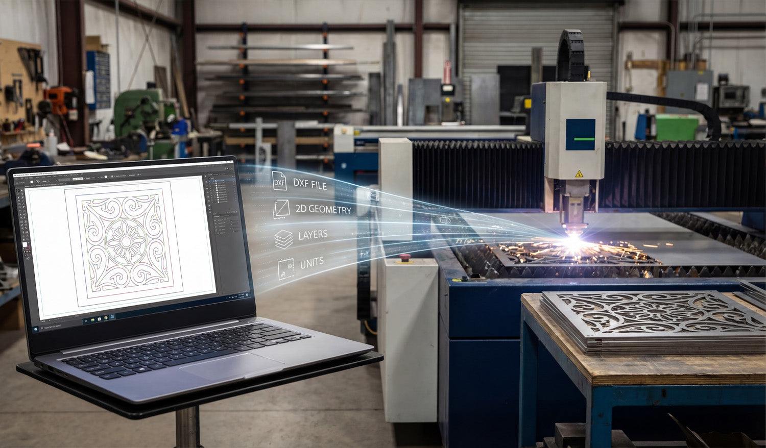
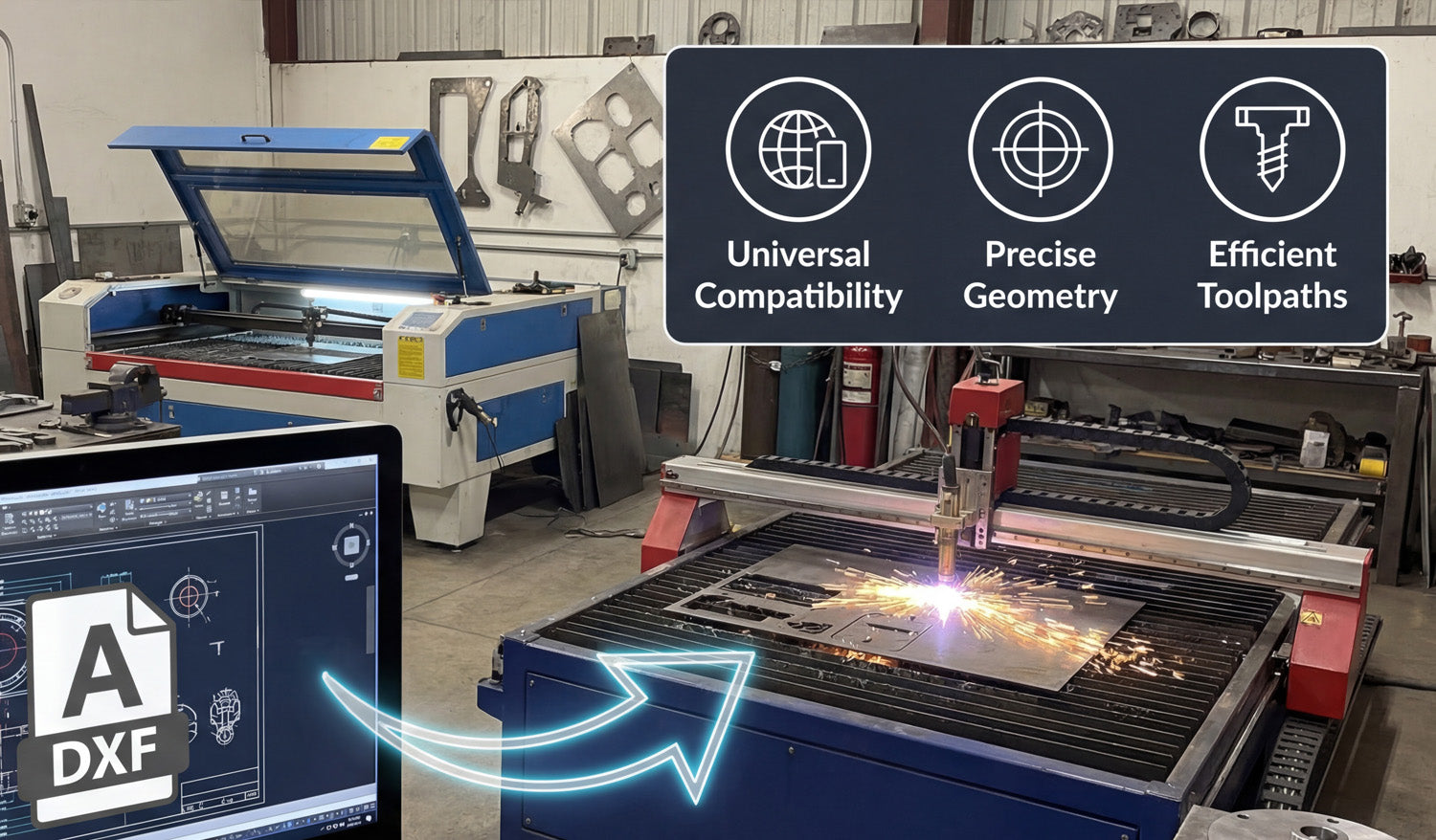
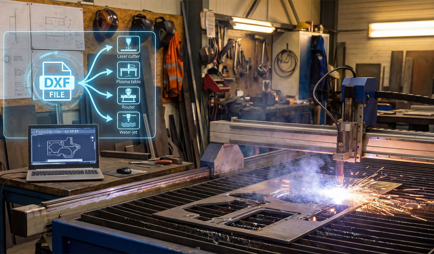
DXF files act as the “common language” between your design software and CNC cutting machines, carrying clean 2D geometry, layers, and units so lasers, plasmas, routers, and water-jet tables know exactly where to move, where to pierce, and what to cut. What Is a DXF File in the CNC World? DXF (Drawing Exchange Format) was created to let different CAD programs share vector drawings. In CNC cutting, that same format became the standard way to describe 2D shapes like profiles, holes, slots, and engravings. Vector-based: DXF stores lines, arcs, circles, and splines as precise math, not pixels. Neutral format: It is not tied to one brand of CAD or CAM software. 2D-first: Perfect for flat parts cut on laser, plasma, router, and water-jet machines. Instead of sending screenshots or photos to the shop floor, you send a DXF file that the machine can interpret without guesswork. Where DXF Files Sit in the CNC Workflow To understand the role of DXF files, it helps to look at a typical CNC cutting workflow from idea to part: Design: You create or edit a part in CAD or a vector design tool. Export: You save the 2D geometry as a DXF file. CAM / Nesting: CAM software imports the DXF, creates toolpaths, and nests parts on sheets. CNC Machine: The cutting machine runs code generated from those toolpaths. The DXF file is the bridge between “design space” and “machine space,” carrying only the essential 2D information the cutter needs. How DXF Files Communicate Shape and Size CNC cutting machines do not care about colors, gradients, or photos—they care about paths. DXF files provide exactly that. Coordinates: Each line and arc has precise start and end points. Units: Geometry is defined in millimeters or inches (depending on how the file is created). Closed profiles: Outer shapes and inner cutouts can be recognized as complete loops for cutting. When these paths arrive in CAM, the software can easily turn them into toolpaths: inside cuts, outside cuts, and outlines for engraving. The Role of DXF in Different CNC Cutting Machines Almost every 2D CNC cutting process can use DXF files, but each machine type benefits in slightly different ways. Laser Cutting Machines Lasers use DXF geometry to cut very fine details in wood, acrylic, and thin metals. Separate layers or colors in the DXF can map to cutting vs engraving power settings. Clean, smooth curves in DXF mean fewer pauses and cleaner edges on the finished part. Plasma Cutting Tables Plasma machines rely on DXF files to define bold shapes, holes, and slots in steel, stainless, and aluminum. Properly designed DXF files help avoid blown-out small features and irregular holes. DXF-based nests allow you to fit many heavy parts onto a sheet with efficient cut paths. CNC Routers Routers use DXF files for cutting plywood, MDF, plastics, and soft metals. DXF geometry defines pockets, profiles, and drill hole locations. Tool diameters and step-downs in CAM are based on the exact geometry imported from DXF. Water-Jet Cutting Machines Water-jets use DXF files to cut thick or heat-sensitive materials like stone, composites, and metals. Accurate shapes in DXF help maintain tight tolerances without heat distortion. In all of these cases, the machine type changes—but the DXF remains the standard way to describe the cut path. DXF Layers: Organizing Operations for the Machine Beyond just shapes, DXF files can store layers that help you tell the machine what each path should do. CUT_OUTSIDE: Outer profiles for final part edges. CUT_INSIDE: Holes, slots, windows, and internal cutouts. ENGRAVE / ETCH: Logos, text, part numbers, bend lines, or weld marks. REFERENCE: Centerlines, dimensions, and construction geometry not meant to be cut. In CAM or controller software, you can map these layers to different tools, speeds, and power levels, turning one DXF into a complete cutting plan. DXF Files and Kerf Compensation DXF geometry describes the “ideal” shape. The machine then has to account for kerf—the width of the cut made by a laser beam, plasma arc, or router bit. CAM software uses DXF profiles to calculate offset toolpaths inside or outside the line. For tight fits, DXF-based dimensions must be accurate so kerf compensation produces the correct final size. When you learn how your machine behaves, you can build that knowledge into your DXF designs (for example, slightly oversizing small holes). In this way, DXF files play a direct role in how precise and repeatable your finished CNC parts will be. DXF as a Shared Language Between Teams and Tools In real shops, designers, programmers, and machine operators often use different software. DXF makes it possible for everyone to work together. Designers create parts in their favorite CAD or graphics tool and export as DXF. CAM programmers import the DXF into nesting or toolpath software. Operators run the resulting CNC code on different machine brands. Because DXF is widely supported, you are not locked into one software ecosystem. You can swap machines, change CAM packages, or bring in outside help without needing to redraw your entire library. DXF Files in Prototyping vs Production The role of DXF files shifts slightly depending on whether you are making a one-off prototype or running a large batch. Prototyping DXF files let you quickly iterate on shapes, hole positions, and clearances. You can tweak a few dimensions, export a new DXF, and cut another test part in minutes. Once the shape works, you save that DXF as your “approved” geometry. Production DXF files become part of a controlled library—each with a drawing number and revision. CAM and nesting templates are built around standardized DXF layers and naming. Repeat orders use the same DXF geometry, ensuring consistent parts across batches and machines. In both scenarios, DXF files are the geometry source of truth that the rest of the CNC process depends on. Handling Customer-Supplied DXF Files Many shops receive DXF files directly from customers. In those cases, the DXF’s role includes both opportunity and responsibility. Opportunity: You can skip the design stage and move straight into checking, cleaning, and programming. Responsibility: You must verify units, scale, closed paths, and feature sizes before cutting. Communication: If something is off—like hole sizes or material thickness—you use the DXF as a clear reference when talking to the customer. A well-prepared customer DXF can go from inbox to machine very quickly; a poor one needs editing before it is safe to use. Common DXF Issues That Affect CNC Machines Because DXF files sit between design and cutting, problems in the file often show up as problems on the machine. Open contours: Paths that are not fully closed can be skipped or misinterpreted by CAM. Duplicate entities: Overlapping lines cause double cuts, rough edges, and wasted time. Too many nodes: Overly dense curves make machines slow down and produce faceted edges. Wrong units: Files drawn in inches but loaded as mm (or vice versa) create parts at the wrong size. Understanding these issues helps you see why good DXF practices are so important to CNC machine performance. Why DXF Files Still Matter in Modern CNC Shops Even as 3D CAD and more advanced formats grow, DXF files remain crucial for flat cutting work. Most flat parts—brackets, gussets, panels, signs, fixtures—are still cut from 2D profiles. CAD users can easily extract 2D views from 3D models and export them as DXF. Legacy designs and old projects are often stored as DXF and still cut perfectly today. This long-term stability is why so many shops still center their 2D cutting workflows on DXF files. Conclusion DXF files play a central role in CNC cutting machines by translating design intent into machine-ready geometry that lasers, plasmas, routers, and water-jets can understand. They carry the outlines, holes, layers, and units that CAM systems need to build toolpaths and that operators rely on for repeatable, accurate parts. When you master how DXF files fit into the CNC workflow—from clean design and layer management to kerf-aware geometry—you gain tighter control over quality, speed, and consistency across every cutting project.

CNC for Hobbyists: How to Use DXF Files for Personal Projects
CNC for hobbyists becomes a lot more fun and a lot less frustrating when you understand how to use DXF files for your personal projects—whether you are making wall art, workshop jigs, cosplay props, or custom gifts. What Is a DXF File and Why Should Hobbyists Care? DXF (Drawing Exchange Format) is a vector file type that stores shapes as lines, arcs, and curves instead of pixels. For a hobby CNC user, this means: Clean shapes: Your CNC follows exact paths instead of “fuzzy” edges from images. Easy scaling: You can resize designs without losing quality. Wide compatibility: Most CAD, CAM, and CNC programs can import DXF files directly. If you have ever tried to cut from a JPG and ended up with messy toolpaths, switching to DXF will feel like a big upgrade. Typical DXF-Based Projects for CNC Hobbyists DXF files are perfect for many personal CNC projects, including: Decorative wall art and signs in wood, metal, or acrylic. Workshop jigs, templates, and measuring tools. Custom name plates, key holders, and door signs. Cosplay and prop parts cut from foam, MDF, or plastic. Layered 3D panels and inlays for furniture or decor. Instead of drawing everything from scratch, you can start from ready-made DXF designs and adapt them to your own style. Step 1: Choose the Right CNC Machine and Material Before you download or design any DXF, think about what you are cutting with and what you are cutting into. Laser cutters: Great for thin wood, MDF, acrylic, and light engraving. CNC routers: Ideal for plywood, solid wood, plastics, and soft metals (with the right setup). Small plasma tables: Good for hobby metal art and brackets, but with a wider kerf than lasers. Once you know your machine and typical material thickness, you can pick DXF designs that match what your setup can realistically handle. Step 2: Find or Download DXF Files for Personal Use You do not need to be a CAD expert to enjoy CNC. There are many ready-to-use DXF designs made for hobbyists. Look for: Free sample files: Many sites (including ours) offer free DXF files you can try on your machine. Project-based bundles: Collections focused on wall art, animals, signs, or workshop tools. License clarity: Check whether a file is allowed for personal use only or also for selling finished products. Starting with proven DXF files lets you test your machine and settings before you move on to your own custom designs. Step 3: Open DXF Files in Your CAD or CAM Software Once you have a DXF file, the next step is to bring it into software that connects to your CNC. Import the DXF into your CAM program or CAD/CAM combo software. Check the scale and units (millimeters or inches) and measure one known dimension. Make sure all shapes are closed paths with no gaps or duplicated lines. Separate cut lines and engraving lines onto different layers or colors if your software supports it. This quick check prevents surprises like oversized parts or incomplete cuts when you start the job. Step 4: Resize and Customize DXF Files for Your Project One of the best parts of DXF-based projects is how easy it is to customize them for your space or ideas. Scale up or down: Adjust the overall size to fit your material and project area. Add holes or slots: Include mounting holes, hooks, or screw points for hanging and assembly. Edit text: Replace generic words with names, dates, or quotes. Combine designs: Merge two or more DXF files into one unique layout. Just remember that if you scale a design too small, very thin details might become too weak to cut cleanly. Step 5: Match Detail Level to Your Hobby CNC Setup Not every hobby machine can cut ultra-fine detail, and that is okay. The key is to match design complexity to your tool. For small lasers, you can keep more detail in thin plywood or acrylic, but still avoid hairline bridges. For desktop routers, make sure narrow gaps are wider than your bit diameter. For hobby plasma, use bold shapes and thicker webs so parts stay strong. If a DXF looks extremely detailed on screen, consider simplifying it a bit before cutting on a small or entry-level machine. Step 6: Set Up Toolpaths and Cutting Parameters With the DXF imported and adjusted, it is time to tell your machine how to move. Assign inside cuts for holes and internal shapes, and outside cuts for outer profiles. Select feed rates, speeds, power, and depth based on your material and tool. Add tabs if necessary so small parts do not shift or fall out during cutting. Simulate the job in your CAM software to confirm the order and direction of cuts. Even as a hobbyist, taking a moment to simulate toolpaths can save material and frustration. Step 7: Run Test Cuts and Keep Notes Your first cut with a new DXF is a learning experience. Treat it like a test run, not a failure if something needs adjustment. Use scrap material or cut a smaller version of the design first. Note which settings produced clean edges and good fits. Adjust scaling, kerf compensation, or feed rates if holes are tight or edges look rough. Write your best settings on a label, in a notebook, or in a digital log for next time. Over time, your personal notes become a hobby “playbook” that makes future projects much easier. Safety and Practical Tips for Hobby CNC Users Even for personal projects in a garage or small workshop, safety and basic practice still matter. Wear eye protection and follow your machine’s safety guidelines. Use proper dust collection or ventilation when cutting wood, plastics, or metals. Secure your material firmly to avoid shifting or tipping during cuts. Stay nearby while the machine is running, especially on new designs. A careful approach keeps CNC as an enjoyable hobby instead of a stressful one. Ideas to Grow Your CNC Hobby with DXF Files Once you are comfortable using DXF files, you can: Build a small library of favorite designs that you reuse for gifts and personal decor. Experiment with layered projects using multiple DXF shapes stacked at different depths. Create custom fixtures and jigs that make your other DIY projects easier. Slowly move toward selling finished pieces locally or online, if the license on your DXF files allows it. The more you practice, the more your CNC hobby turns into a powerful creative tool for both fun and potentially side income. Conclusion For hobbyists, DXF files are the key to unlocking the full potential of small CNC machines. They let you start from clean, accurate designs, customize them to fit your ideas, and run them confidently on lasers, routers, or plasma tables. With a simple workflow—find a DXF, clean it, customize it, test it—you can turn personal project ideas into real, physical pieces that look professional even in a home workshop.
Why You Should Choose DXF Files Over Other Formats for CNC Projects
Choosing DXF files over other formats for CNC projects keeps your geometry clean, your workflow predictable, and your machines compatible across different software and hardware. File Format Can Make or Break a CNC Job If you run a CNC machine long enough, you see the same pattern: good designs ruined by the wrong file format. Someone sends a logo as a tiny JPG, a drawing as a proprietary CAD file nobody can open, or a vector with broken paths. You spend more time fixing files than cutting parts. DXF (Drawing Exchange Format) was created to solve exactly this problem. It acts as a common language between CAD, CAM, and CNC systems, especially for 2D cutting like laser, plasma, router, and water-jet. 1. DXF Is Designed for Exact CNC Geometry DXF stores geometry as real vectors: lines, arcs, circles, and splines with exact coordinates. That makes it ideal for CNC cutting. No pixel guessing: Unlike JPG or PNG, DXF does not need to be “traced.” The shapes are already clean vectors. True arcs and circles: Holes, slots, and radii stay round and smooth, not made of tiny jagged segments. Consistent dimensions: What you draw at 100 mm in CAD arrives as 100 mm in CAM when units are set correctly. For tight fits, bolt patterns, and precise contours, this level of accuracy is non-negotiable. 2. DXF Works with Almost Every CAD, CAM, and CNC System One of the biggest reasons to choose DXF is simple: everybody understands it. Most CAD programs can export and import DXF without extra plugins. Most CAM packages can read DXF directly for 2D toolpaths. Many laser and plasma controllers import DXF as a primary format. That means you can design in one program, nest in another, and cut on a different machine brand without redrawing from scratch or fighting conversions. 3. DXF Beats Raster Images for CNC Every Time People often start with logos, artwork, or photos in formats like JPG or PNG. Those are fine for screens, but not for CNC machines. Raster formats: Store pixels. Your software must guess where edges are when you trace them, creating noisy paths. DXF: Stores curves and lines directly. No tracing, no “close enough” edges, no random bumps in your toolpath. If you begin with a raster image, the best practice is to convert it into clean vector artwork and export as DXF for CNC. That conversion step is where you fix the geometry—DXF is where you lock it in. 4. DXF Is More CNC-Friendly than Many Native CAD Formats Native CAD files (DWG, proprietary 3D formats, parametric models) are great for engineering, but they are not always ideal for the shop floor. They may require the same software (and license) used to create them. They can contain a lot of extra data you do not need for cutting. They sometimes import unpredictably into third-party CAM systems. DXF is lighter and focused on 2D geometry. When your goal is to cut a flat part, not rebuild a parametric model, DXF is usually the most direct route from design to toolpath. 5. DXF Handles Layers and Colors for CNC Operations One of DXF’s biggest superpowers is layer support. This matters a lot for multi-step CNC jobs. You can create separate layers for outside cuts, inside cuts, engraving, scoring, and reference geometry. Many laser and plasma controllers can map colors or layers directly to different power, speed, or pierce settings. Reference geometry (centerlines, dimensions, notes) can live in the file without being cut. Other vector formats like SVG can handle layers too, but DXF is the one most CAM and CNC tools were built to understand in a manufacturing environment. 6. DXF Plays Nicely with Kerf Compensation and Toolpaths For CNC cutting, geometry is only half the story. You also need to consider kerf (cut width) and inside/outside compensation. DXF stores clean closed profiles that CAM software can easily offset for kerf. Inside and outside contours are easier to detect when shapes are well-defined in DXF. Plasma and laser CAM systems are typically tuned to work best with DXF inputs. Other formats might carry vectors too, but DXF has become the “native language” for 2D kerf-based processes in many shops. 7. DXF Files Are Easier to Inspect and Troubleshoot When a CNC job fails, you often ask: “Is it the machine, the CAM settings, or the file?” With DXF, the file part is easier to check. Free viewers and basic CAD tools can open and zoom into DXF to inspect geometry. You can quickly spot open paths, duplicate lines, or stray entities and fix them. Because DXF is widely documented, it is simpler to understand what is actually inside the file. Trying to debug native, locked-down formats or flattened artwork is usually harder and slower. 8. DXF Supports Long-Term Storage and Reuse File formats come and go as software changes, but DXF has been around for decades and is still the standard in many CNC workflows. It is well documented, so future tools will likely continue to support it. It is human-readable at a basic level (text-based variants), giving you some protection against format lock-in. You can safely archive DXF libraries and expect them to be usable years later, even if your CAD system changes. That makes DXF a smart choice for long-term design libraries, product lines, and recurring CNC jobs. 9. DXF Works Well Alongside Other Formats Choosing DXF does not mean you must abandon every other format. Instead, you use each one where it makes sense: AI / SVG: For creative artwork and design stages. Native CAD: For 3D modeling, assemblies, and parametric design. DXF: As the final, clean 2D profile you send into CAM and CNC. Think of DXF as the “production language” for your cutting machines—a stable, CNC-ready version of whatever design path you used to get there. 10. When DXF Should Be Your Default Choice If your project involves 2D cutting or engraving on a CNC machine, DXF is almost always the safest default. It is especially strong when: You share files between different shops, partners, or machines. You run laser, plasma, water-jet, or router tables for flat parts. You maintain a large library of reusable designs that must outlive any single software tool. In these scenarios, other formats may still appear in your workflow, but the file that feeds the machine is typically DXF. Quick Comparison: DXF vs Other Common Formats Format Best For CNC Suitability DXF 2D CNC cutting, CAD exchange Excellent – native choice for many CAM/CNC tools JPG/PNG Photos, mockups, web Poor – needs tracing, low precision SVG/AI Artwork, logos, design Good for design, but less universal in CAM than DXF Native CAD (DWG, etc.) Engineering, 3D models Requires matching software; extra conversion step Conclusion DXF files give CNC projects a huge advantage: precise vector geometry, universal compatibility, clean layer control, and long-term reliability. While other formats still have a place for design, artwork, and 3D modeling, DXF is the format you can trust when it is time to move from screen to steel, wood, acrylic, or aluminum. Choosing DXF as your standard for CNC projects means fewer surprises, faster setup, and more consistent results on every job.
Why DXF Files Are a Must for High-Precision CNC Projects
DXF files are essential for high-precision CNC projects because they carry clean, exact vector geometry from your CAD software to the machine without guesswork, distortion, or hidden surprises. High Precision Starts with Reliable Geometry Every tight-tolerance CNC part begins as a drawing. If that drawing is fuzzy, approximate, or full of errors, the finished part will be the same. DXF (Drawing Exchange Format) was created to move precise 2D geometry between different systems while keeping: Exact coordinates for lines, arcs, and curves. Stable units (millimeters or inches) that do not shift on import. Predictable entities that CAM software can turn into accurate toolpaths. For high-precision work—fixtures, plates, jigs, brackets, and templates—this level of geometric reliability is non-negotiable. DXF vs. Image-Based Files: No More Guessing One of the easiest ways to lose precision is to start from the wrong file type. Bitmaps and screenshots may look fine on screen, but they force your software to guess at edges. Raster images (JPG, PNG, TIFF) store pixels, not coordinates. When you trace them, tiny stair-steps and noise become part of the geometry. DXF files store pure vector data. Every corner and radius is defined by numbers, not by pixel edges. That difference matters when you are cutting tight-fitting tabs, aligned bolt patterns, or parts that must repeat perfectly from one batch to the next. Consistent Units and Scale for Tight Tolerances Precision is impossible if you are not sure how big the part really is. DXF is designed to keep units and scale under control. You define units once in CAD (mm or inches); the DXF passes that geometry directly to CAM. Dimensions and reference lengths in the DXF let you verify size after import. Scaling mistakes—parts 10× too big or small—are easy to spot and avoid. For high-precision CNC work, this consistency means less time measuring and more time cutting parts you can trust. Layer Control for Multi-Step Precision Jobs High-precision projects often mix different operations on the same part: through cuts, counterbores, engraving, and reference marks. DXF layers make this complexity manageable. Separate layers for outside profiles, pockets, holes, engraving, and reference edges. Each layer can map to different tools, depths, feeds, and speeds in CAM. Reference geometry (centerlines, datums, alignment marks) stays in the file without ever being cut. This layer structure helps you align critical features, maintain datums, and repeat complex setups with the same accuracy every time. Exact Curves for Smooth Toolpaths High precision is not just about hitting the right size—it is also about smooth motion. DXF describes arcs, circles, and splines numerically, so CAM can generate continuous, flowing toolpaths. True arcs cut cleaner holes and slots than lots of tiny line segments. Consistent radii reduce stress concentrations and make parts easier to finish. Optimized node counts avoid “stop-and-go” motion that leaves faceted edges on tight curves. When your high-precision design includes bearing fits, dowel pin holes, or smooth mating surfaces, DXF-based arcs make the difference between “close enough” and “right on size.” DXF as the Glue Between Different CAD/CAM Systems Many high-precision environments use more than one software tool: one for design, another for simulation, and a third for CAM or nesting. DXF is the common language that keeps geometry consistent across all of them. Design in your main CAD software, export a DXF, and import it into whatever CAM is best for your machine. Share DXF drawings with suppliers or partners and know they can open them on their own systems. Move legacy parts from older CAD tools into new workflows without redrawing from scratch. When teams, machines, and software change over time, DXF protects the precision built into your original design. Supporting Tight Fits, Jigs, and Repeatable Fixtures Some of the most demanding CNC parts are not flashy—they are the jigs and fixtures that hold everything together. DXF fits naturally into this world. Fixture plates: Bolt patterns and dowel layouts stay aligned between different parts and revisions. Drill templates: Hole locations transfer from CAD to the shop floor without tape measures and layout dye. Assembly jigs: Slots, pins, and stops line up exactly, job after job. Once a DXF-based fixture proves accurate on the machine, you can reuse and re-cut it on demand with complete confidence. Kerf and Compensation: Designing for Real-World Accuracy DXF files are also a natural place to embed kerf-aware geometry for high-precision fits. Slots and tabs can be drawn with the expected kerf and clearance already considered. Standard hole sizes in the DXF match standard tool diameters or kerf-compensated laser/plasma paths. Outer profiles and inner features are ready for inside/outside compensation without guesswork. When CAD, DXF, and CAM all agree about kerf and tolerances, you spend far less time filing and reworking “almost right” parts. Traceability and Documentation for Quality Work High-precision work often needs traceability—especially in aerospace, automotive, and industrial applications. DXF supports this kind of disciplined workflow. Each revision of a DXF can be tied to a drawing number, date, and version in your documentation. Inspection teams can use the DXF as a reference for CMM programs or manual checks. Suppliers can receive the same DXF that your internal team uses, reducing misinterpretation. This combination of clear geometry and documented revisions helps you prove that parts were made to the correct design, not just “close enough.” Real-World Example: High-Precision Mounting Plate Imagine a mounting plate that connects a motor to a gearbox. The bolt pattern, pilot diameter, and key slots must all align perfectly. With a well-prepared DXF: The bolt circle and center bore come directly from CAD, not from rough measuring. Toolpaths follow true circles and arcs, producing round, repeatable fits. Multiple plates cut from different batches match each other within the expected tolerance. Without DXF-level control, you are back to transferring hole locations by hand and hoping they line up from job to job. DXF in Mixed 3D/2D Precision Workflows Even in 3D-heavy environments, precise 2D profiles still matter: for gaskets, shims, cover plates, base plates, and laser-cut blanks. CAD users extract 2D views or sections from 3D models and export them as DXF. Those DXF profiles drive laser, water-jet, or router tables to produce finished blanks. The final parts fit into larger assemblies with no manual shaping or adjustment. In this mixed workflow, DXF is the bridge between 3D design intent and flat, high-precision components on the shop floor. Conclusion DXF files are a must for high-precision CNC projects because they deliver exactly what tight-tolerance parts need: clean vectors, consistent units, layer-based control, and a stable bridge between design and machining. Whether you are cutting small brackets, complex fixtures, or mission-critical plates, a carefully prepared DXF lets your CNC machines do their best work—accurate, repeatable, and ready for serious production.
The Best Tools for Working with DXF Files in CNC Projects
Using the right software tools for working with DXF files in CNC projects can save you hours of cleanup, reduce scrap, and help your laser, plasma, router, or mill run smoother and more profitably. Why Your DXF Toolchain Matters A DXF file is the bridge between your design ideas and your CNC machine. If you only use basic viewers or random editors, you end up fighting bad geometry, scale issues, and messy imports. A good DXF toolchain covers three main jobs: Creating and editing DXF designs (CAD and vector tools). Cleaning and optimizing DXF geometry for CNC. Converting DXF into CNC-ready toolpaths (CAM and controller software). Below are some of the best tool types to consider and how they fit into a clean, CNC-friendly workflow. 1. CAD Software for Drawing and Editing DXF Files CAD (Computer-Aided Design) software is often the primary tool for creating and editing DXF files. These tools give you precise control over dimensions, layers, and geometry. Professional CAD systems: Ideal when you need full control over dimensions, constraints, layers, and parametric design. Great for mechanical parts, brackets, fixtures, and sheet-metal patterns. 2D drafting tools: Lighter-weight alternatives focused on 2D drawings. Often enough for flat panels, signs, and decorative work. Key features to look for: Reliable DXF import/export with multiple version options. Support for layers, colors, and line types. Powerful snap and constraint tools for precise geometry. Options to simplify curves and manage node counts. If your CAD system can produce clean DXF files with correct units and layers, every other step in your CNC workflow becomes easier. 2. Vector Graphics Editors for Artwork and Logos For signs, wall art, logos, and decorative panels, vector graphics software can be just as important as CAD. These tools are great for freeform artwork that still needs to export as DXF. Ideal use cases: Logos, text-based designs, monograms, ornaments, and intricate line art. Useful features: Converting text to outlines so it engraves or cuts correctly. Path operations like union, subtract, and intersect for building complex shapes. Control over strokes vs fills to match your laser or router workflow. Export options for DXF and SVG, often used together in CNC jobs. When paired with a CAD tool, a vector editor lets you blend clean engineering geometry with creative artwork inside the same DXF pipeline. 3. DXF Viewers and Quick Inspection Tools Before a file ever reaches CAM or a CNC machine, a simple DXF viewer can help you catch obvious problems quickly. What these tools are best for: Checking overall size and verifying units. Inspecting layer structure and colors. Looking for broken profiles or missing details. Benefits: They are fast, lightweight, and easy for operators to use without touching the master design file. Using a dedicated viewer as a “first pass” saves time and keeps accidental edits out of your main CAD projects. 4. DXF Cleanup and Optimization Utilities Even well-designed DXF files can pick up errors: duplicate lines, tiny gaps, or too many nodes from tracing or heavy editing. Cleanup tools are designed to fix these issues. Key cleanup functions: Remove duplicates: Deletes overlapping lines that cause double cuts. Close gaps: Joins near-miss endpoints into fully closed contours. Simplify paths: Reduces node count on curves while preserving shape. Remove junk geometry: Gets rid of tiny islands, stray points, and unused blocks. Why this matters: Cleaner DXF geometry means faster toolpaths, fewer crashes, and better surface quality on your CNC machine. You can often do basic cleanup inside CAD or vector editors, but specialized tools or scripts can save time when you process lots of files. 5. CAM Software for Turning DXF into Toolpaths CAM (Computer-Aided Manufacturing) software is where your DXF becomes real machine motion. This is a critical part of any CNC toolkit. For lasers and plasmas: Import DXF and assign cut, engrave, and score operations. Set power, speed, frequency, and cut order. Apply kerf compensation and generate optimized toolpaths. For routers and mills: Turn DXF contours into profiles, pockets, and drilling cycles. Manage tools, stepdowns, stepovers, and finishing passes. Handle multiple setups and work coordinate systems when needed. What to look for: Good DXF handling, solid simulation, and a post-processor that matches your specific controller. Strong CAM software is what turns your DXF library into production-ready CNC code. 6. Nesting Software for Sheet-Based CNC Cutting If you cut a lot of parts from sheet material (metal, plywood, acrylic), nesting tools are a must-have. They work hand-in-hand with DXF files. Core functions: Import multiple DXF parts and arrange them on a sheet. Automatically rotate and pack parts to maximize material use. Separate jobs by material, thickness, and machine. Benefits: Less scrap, fewer sheets used, and cleaner job organization. Some CAM systems include basic nesting; dedicated nesting tools often give better control and tighter layouts, especially for production shops. 7. Text and Font Tools for DXF-Based CNC Projects Text is a surprisingly tricky part of many CNC jobs—especially for cut-out signs and stencils. Specialized text tools help you convert fonts into safe, CNC-ready vectors. Important capabilities: Convert text to outlines while maintaining good curve quality. Create stencil fonts where inner islands of letters are bridged. Adjust spacing and stroke thickness for readability after cutting. Why it matters: Good text tools prevent letters from falling apart and make signs, nameplates, and monograms look professional. 8. Measurement and Inspection Tools Inside DXF Editors A lot of DXF work is about verifying that designs match your real-world needs. Built-in measurement and inspection tools in CAD/vector editors are essential. Use distance and angle tools to verify critical dimensions. Check hole spacing and slot widths for fit with mating parts. Measure bridge widths and minimum feature sizes against your kerf and material limits. These simple tools help you catch design issues before they show up as scrap on the CNC table. 9. Scripting and Automation Tools for Bulk DXF Work If you handle large numbers of DXF files, scripts and automation tools can be game-changers. What you can automate: Batch renaming and organizing DXF libraries. Automatic cleanup steps (remove duplicates, delete certain layers). Exporting multiple formats from a master design set (DXF, SVG, PDF). Where they run: Inside CAD software as macros, in separate automation tools, or via command-line scripts. For serious CNC businesses with big design catalogs, a small investment in automation can save huge amounts of repetitive work. 10. File Management Tools for DXF Libraries As your DXF collection grows, simple file storage is not enough. You need a system. Folder structure: Organize by process (Laser, Plasma, Router), then by category (Animals, Signs, Panels, Brackets). Naming standards: Include size, material, and version in filenames where it matters. Backups and sync: Use backup tools or cloud sync so your DXF library is safe and accessible from multiple machines. Good file management tools keep your DXF designs from getting lost and help operators quickly find the right file for each job. How to Build Your Ideal DXF Tool Stack You do not need every tool on this list on day one. Start from your main CNC process and build from there: Pick a CAD or vector editor you like for design and basic editing. Add a CAM package that works well with your machine and imports DXF cleanly. Introduce cleanup and nesting tools as your job volume grows. Layer in automation and library management when you are handling many designs or running production. Over time, refining your DXF tool stack is one of the most effective ways to improve CNC productivity without changing your hardware at all. Conclusion The best tools for working with DXF files in CNC projects are the ones that cover your full workflow—from accurate drawing and clean geometry to smart nesting and reliable toolpaths. By combining strong CAD and vector tools, dedicated cleanup utilities, capable CAM software, and solid file management, you can turn raw DXF designs into CNC-ready jobs with less friction and more control. Build your stack step by step, and your DXF files will become a true competitive advantage for every laser, plasma, router, and milling project you run.

Why DXF Files Are Ideal for Detailed CNC Projects
DXF files are ideal for detailed CNC projects because they store precise vector geometry, handle complex shapes, and work reliably across most CAD, CAM, and CNC systems. What Makes a CNC Project “Detailed”? Not all CNC jobs are simple rectangles and bolt holes. Many real projects include: Fine decorative patterns and filigree. Intricate metal art and wall panels. Logos, lettering, and monograms. Complex slot-and-tab assemblies. Multi-part layouts with many small features. These detailed CNC projects demand clean geometry, stable scaling, and accurate toolpaths. That is exactly where DXF files shine. Vector-Based Geometry for Sharp Detail DXF files store shapes as vectors—lines, arcs, and curves defined by math, not pixels. This has several benefits for detailed CNC work: Infinite zoom: You can zoom in on tiny areas without losing clarity or introducing blur. Smooth curves: Arcs and splines produce flowing motion on the machine instead of jagged, stair-stepped edges. Precise control: You can define exact radii, angles, and distances for every element of the design. For intricate signs, patterns, and artwork, this vector foundation is essential to keep detail crisp and accurate. Excellent Support Across CNC Software and Machines DXF is one of the most widely supported formats in the CNC world. This is especially important for detailed projects, which often move through multiple tools and workflows. Design tools: Most CAD and vector programs can open, edit, and save DXF files. CAM systems: Laser, plasma, router, and water-jet CAM software almost always support DXF import. Machine controllers: Many controllers or their companion tools read DXF directly or through a simple conversion step. When you work with complex detail, you do not want to redraw your design just to switch software or machines. DXF lets you keep a single, consistent design file across your entire workflow. Layers and Colors for Organizing Complex Operations Detailed CNC projects often require more than one kind of operation. DXF files support layers and, in many systems, colors that can be mapped to different tasks. Use one layer for outer profiles, another for inner cutouts. Place engraving, scoring, or marking on separate layers. Keep construction lines, guidelines, and notes on a non-cutting layer you can hide later. This structure makes it much easier to manage detailed designs with thousands of elements. You can quickly turn operations on or off, adjust settings layer by layer, and avoid mistakes during setup. Clean Scaling Without Losing Detail Because DXF files are vector-based, they scale up or down without becoming blurry or blocky. For detailed CNC projects, that means: You can create multiple size versions of the same design (small, medium, large) from the same DXF. Logos and artwork stay sharp even when resized for different products. You can adapt one design to different machines and sheet sizes by scaling it appropriately. The key is to check minimum feature sizes after scaling. As long as your smallest bridges, gaps, and text remain above your machine’s cutting limit, DXF handles detail very well at varying scales. Better Toolpath Generation for Intricate Shapes CAM software can generate much better toolpaths when it receives clean DXF geometry. This is especially important for projects with many small curves, corners, and internal cutouts. Stable motion: Smooth DXF curves translate into steady movement, which improves edge quality. Smarter ordering: CAM tools can easily cut inner features first, then outer profiles, to protect fine details. Controlled kerf compensation: With predictable geometry, you can apply kerf offsets and still keep delicate shapes accurate. For detailed metal art or technical parts, this combination of clean input and intelligent toolpaths is crucial for success. Easy Editing and Iteration for Complex Designs Detailed CNC projects rarely stay the same forever. Customers want changes, dimensions shift, and you may want to refine the design for faster cutting. DXF files make these adjustments easier. You can edit individual nodes and curves without redrawing the entire part. You can add or remove detail in specific areas while keeping the rest of the design intact. You can use boolean tools (union, subtract, intersect) to merge or modify complex shapes. Instead of starting from scratch, you can keep improving your DXF over time and build a richer, more refined library of detailed designs. Reliable Reuse for Product Lines and Repeat Jobs Once you have a detailed DXF design that cuts well, it becomes a reusable asset. Use the same design across different materials (steel, stainless, aluminum, wood, acrylic). Offer multiple versions of a product line simply by adjusting size and thickness in your CAM setup. Run repeat orders with confidence, knowing the design has already been tested and optimized. Over time, a library of proven DXF files for detailed CNC projects can become a major competitive advantage for your shop or brand. Handling High Detail on Different CNC Machines Laser Cutting Lasers are ideal for fine detail, and DXF geometry lets them follow extremely tight paths. DXF-based designs help you dial in power and speed while keeping delicate areas intact. Plasma Cutting Plasma has a wider kerf, but a good DXF lets you manage detail within those limits. By controlling minimum feature size in your DXF, you can still achieve impressive detail in metal art and signs. CNC Routers Routers rely on bit diameter; DXF files allow you to design corners, pockets, and contours that respect tool size. Detailed inlays, signs, and 2.5D carvings all benefit from precise DXF geometry. Tips for Getting the Most Detail from DXF Files Start with clean vectors: Avoid auto-traced artwork that is noisy or overloaded with nodes. Design with real kerf in mind: Make sure your smallest elements are larger than your tool width. Test cut small sections: Try a portion of your detailed design on scrap material before running a full sheet. Optimize curves: Simplify excessive nodes for smoother machine motion without losing important shape. Organize layers: Use layers for different detail levels, like fine engrave paths versus full-depth cuts. Conclusion DXF files are ideal for detailed CNC projects because they combine precise vector geometry, strong software support, layer-based organization, and easy scalability. Whether you are cutting intricate metal art, branded signage, or complex mechanical parts, a well-prepared DXF file gives your CNC machine the clear instructions it needs to reproduce even the smallest details with confidence. By designing, organizing, and testing your DXF files carefully, you unlock the full potential of detailed CNC work on laser, plasma, router, and other cutting systems.
Exploring the Benefits of Using DXF Files for Laser and Plasma Cutting
Using DXF files for laser and plasma cutting gives you cleaner toolpaths, easier workflows, and more consistent results across different machines and materials. Why DXF Files Work So Well for Laser and Plasma Cutting Laser and plasma cutters both rely on precise 2D paths to move the beam or torch around your material. DXF (Drawing Exchange Format) files store those paths as vectors: lines, arcs, and curves defined by coordinates. That makes DXF a natural fit for any sheet-cutting process where accuracy, repeatability, and clean motion really matter. Instead of guessing from a pixel-based image, your machine reads exact geometry from the DXF and turns it into stable, efficient toolpaths. Benefit 1: Universal Compatibility Across CAD and CAM Software One of the biggest advantages of DXF is that almost every CAD, CAM, and CNC control program can read it. This helps you: Design anywhere: Create or edit your drawing in your favorite CAD or vector software. Cut on many systems: Import the same DXF into different laser or plasma CAM tools. Share with others: Send DXF files to customers, suppliers, or partner shops without worrying about software brands. For a busy laser or plasma shop, that compatibility means less time fighting file formats and more time actually cutting parts. Benefit 2: Clean Vector Geometry for Precise Cutting Laser and plasma cutters do their best work when they receive smooth, continuous curves and straight lines. DXF is built around exactly that kind of geometry. Smoother edges: Well-drawn DXF curves produce neat, flowing motion on the machine. Accurate shapes: True arcs and circles cut more consistently than shapes approximated from low-resolution images. Predictable kerf: Clean geometry makes it easier to apply kerf compensation and hit your final dimensions. Whether you are cutting detailed wall art or tight-tolerance brackets, DXF gives you a solid base for accurate results. Benefit 3: Faster, More Efficient Toolpaths When your input geometry is clean, your CAM software can generate better toolpaths for laser and plasma cutting. Reduced pierces: DXF files that use continuous contours allow the CAM system to combine segments and minimize pierce points. Optimized cut order: Inner shapes can be cut before outer profiles, reducing part movement and waste. Less machine “jitter”: Smooth paths keep the head or torch moving consistently, which improves edge quality and speed. Even small improvements in path efficiency can add up, especially when you are running many parts or large nests per day. Benefit 4: Easy Scaling and Reuse DXF files store vector geometry, which scales without losing quality. This is a big advantage for laser and plasma shops that need multiple sizes of the same design. Quickly create small, medium, and large versions of a sign or art piece by scaling the DXF. Reuse the same base file for different material thicknesses or product lines. Keep your design library simple by storing “master” DXFs and creating size variants as needed. This flexibility makes it easier to respond to custom requests and build product families around proven designs. Benefit 5: Better Nesting and Material Utilization Professional nesting software works best with clear, closed shapes—and that is exactly what a good DXF file provides. Tighter nests: Closed, non-overlapping DXF contours allow parts to be packed closely to reduce scrap. Accurate part outlines: Reliable geometry means fewer surprises when parts are removed from the sheet. Consistent margins: Known shapes make it easy to control edge distance and safe spacing between parts. For both laser and plasma cutting, better nesting translates into real savings on steel, aluminum, stainless, or other sheet materials. Benefit 6: One File Format for Both Laser and Plasma Many shops run both laser and plasma cutters, or move jobs between them depending on material and thickness. DXF files make this easy: Use the same design as a fine-detail laser job or a heavy-duty plasma job. Apply different kerf, speed, and power settings in CAM while keeping the DXF geometry identical. Shift production between machines without redrawing the part from scratch. This shared file format lets you match the process—laser or plasma—to the job while keeping your design workflow simple. Benefit 7: Clear Layer and Color Control for Operations DXF supports layers and colors, which many CAM systems use to assign different operations. Separate cut, engrave, mark, and etch paths on different layers. Map each color to a specific power and speed combination on your laser. For plasma, differentiate pierce-only, cut, and mark paths clearly in the DXF. Organized DXF files make it much harder to mix up operations, reducing setup time and costly mistakes on the machine. Benefit 8: Easier Collaboration and Outsourcing If you work with designers, customers, or outside cutting services, DXF is a simple, shared language. Designers can send you DXF files instead of proprietary CAD formats. You can outsource overflow work to other shops that accept DXF-based jobs. Customers can approve proofs and revisions based on the same file that will be cut. This makes your laser or plasma shop more flexible and able to handle larger projects without rebuilding the design from scratch for every partner. Benefit 9: Future-Proof Design Library Because DXF is so widely supported and long-lived, it is a safe choice for building a permanent design library. Old DXF files can still be opened and cut on new software and machines years later. You are less dependent on a single CAD brand or subscription to access your own designs. Your library of signs, art, brackets, and parts becomes a long-term asset for your business. As laser and plasma technology evolves, DXF support is almost guaranteed to remain a core feature in future systems. Conclusion DXF files offer a powerful combination of compatibility, precision, efficiency, and flexibility for both laser and plasma cutting. They help you create cleaner toolpaths, get better edge quality, reduce material waste, and reuse designs across different machines and materials. Whether you are a hobbyist, a small fab shop, or a growing production facility, building your workflow around well-prepared DXF files is one of the smartest moves you can make for reliable, profitable CNC cutting.
Understanding DXF Files: A Beginner’s Guide to CNC Cutting
DXF files are one of the easiest ways to transfer a design from your computer to a CNC machine. This beginner-friendly guide explains, in simple terms, how DXF files work and why they are the foundation of many CNC workflows. What Is a DXF File? DXF stands for Drawing Exchange Format. It is a 2D drawing file that stores lines, arcs, circles, and shapes as precise vector data instead of pixels. In simple terms, a DXF file is a digital blueprint your CNC machine can understand. Because DXF is widely supported by CAD (design) and CAM (toolpath) software, it has become the “universal” format for laser cutters, plasma tables, CNC routers, and many other machines. How DXF Files Fit Into a CNC Cutting Workflow Understanding the role of a DXF file becomes easier when you look at the entire CNC workflow: Design: Create a drawing in CAD software or download a ready-made DXF file. Import: Open the DXF file in your CAM or CNC control software. Toolpaths: Define how the machine will cut — inside, outside, engraving passes, speed, and power. Simulation: Preview the motion to make sure everything looks correct. Cutting: Send the job to the machine and cut the design out of metal, wood, acrylic, or other materials. The DXF file is the bridge between your creative idea and the physical cutting process — the shared language between design and CNC hardware. Why Are DXF Files So Popular in CNC Cutting? Beginners often ask, “Why does everyone use DXF?” Here are the simple reasons: Compatibility: Nearly all CNC-related software can import DXF files. Vector-based: Clean lines and curves make DXF ideal for generating toolpaths. Flexible: You can scale, edit, or combine DXF designs without losing quality. Industry standard: Designers, machine builders, and fabrication shops trust the format. For beginners, this means you can confidently learn CNC using DXF files, knowing they will work on most machines. Which CNC Machines Use DXF Files? DXF files are used across many CNC machine types. The most common include: Laser cutters: Great for thin wood, MDF, acrylic, leather, and metal marking. DXF defines both cutting and engraving paths. Plasma cutting tables: Ideal for steel, stainless steel, and aluminum sheets. DXF is used for signs, brackets, and metal artwork. CNC routers: Used for wood, plastics, foam, and some metals. DXF templates guide profiling and pocketing operations. Waterjet cutters: Perfect for stone, glass, composites, and thick metals. DXF provides the 2D cutting geometry. No matter what machine you start with, learning how DXF files work will make your CNC journey much easier. What’s Inside a Simple DXF File? You don’t need to read DXF code manually, but it helps to understand the building blocks: Entities: Lines, arcs, circles, polylines, and text that form the shapes. Layers: Groups of geometry separated by purpose — such as cut, engrave, or construction lines. Units: The file may be drawn in millimeters or inches, which affects scale on import. When you open a DXF file in CAD or CAM software, you’re essentially viewing the paths your CNC machine will eventually follow. How to Open DXF Files as a Beginner Even if you’re just getting started, you can open and inspect DXF files using many free or affordable tools: Most CAD programs can open DXF files for viewing, measuring, and editing. Many CAM or controller programs let you import DXF files and assign toolpaths directly. Simple DXF viewers allow zooming, panning, and printing without editing. Your beginner goals should be: inspect the geometry, verify the scale, and learn how to send the file to your CNC software. Beginner Tips for Working With DXF Files in CNC Cutting Here are practical tips that help new users avoid common issues: Check the scale: After importing, measure a known feature to confirm the size is correct. Watch for open contours: Outlines should be closed loops — open paths can confuse CAM software. Remove duplicates: Delete any overlapping lines to prevent double-cuts. Use layers wisely: Keep cut, engrave, and reference geometry on separate layers for easier setup. Start simple: Practice on small, basic designs before moving to complex artwork or detailed panels. Test on scrap material: Use scrap for your first run to verify settings and toolpath direction. Common Mistakes Beginners Make With DXF Files Mistakes are normal, but you can avoid the most common ones: Assuming any picture is “CNC-ready”: JPG and PNG images must be converted to clean vector paths before they become usable DXF files. Ignoring material limits: Thin bridges or tiny holes may fail during cutting depending on the material. Skipping cleanup: Gaps, overlaps, and duplicates can cause strange machine behavior. No backups: Editing the only copy can result in losing the original design — always save versions. Learning Faster by Using Ready-Made DXF Files One of the easiest ways to learn is to start with pre-tested DXF designs that already work well on real CNC machines. Instead of spending hours drawing, you can focus on: Importing files into your CAM software. Learning how to adjust power, speed, pierce settings, etc. Understanding cut order, lead-ins, and kerf compensation. Once you feel confident, you can start editing designs or creating your own DXF files from scratch. Conclusion DXF files form the backbone of many CNC cutting workflows, especially for laser, plasma, router, and waterjet machines. As a beginner, you don’t need to master every technical detail right away. But understanding what DXF is, how it fits into the CNC process, and how to spot basic issues will help you learn faster and avoid costly mistakes. With a bit of practice, working with DXF files will feel as natural as opening a regular document on your computer.

What Makes DXF Files the Standard for CNC Cutting?
DXF files became the standard language for CNC cutting because they are simple, open, and work with almost every CAD, CAM, and machine controller. What Is a DXF File? DXF stands for Drawing Exchange Format. It was created as a neutral way for different CAD programs to share 2D drawings. Instead of being locked to one brand or one piece of software, a DXF file can be read by hundreds of programs across Windows, macOS, and Linux. For CNC users, that means you can design in your favorite CAD tool, export as DXF, and then move the file into almost any CAM or control software that drives your laser, plasma, router, or water-jet table. A Short History of DXF in CNC As CNC machines became more common in metal shops, sign shops, and woodworking studios, manufacturers needed a file format that was easy to exchange. DXF spread quickly because: Most CAD software already supported it. Machine builders found it easy to parse and convert to G-code. Shops could send drawings to each other without worrying about which CAD program the other side used. Over time, “Can your machine import DXF?” became one of the first questions people asked before buying a CNC system. That is how DXF quietly became the default standard. Technical Reasons DXF Works So Well for CNC Cutting DXF is not magic, but it has several technical features that make it perfect for 2D cutting work. Vector based: DXF stores lines, arcs, circles, and polylines as precise math, not pixels. That is exactly what a CNC machine needs for clean toolpaths. Unit friendly: Drawings can be created in inches or millimeters, then scaled as needed during import. Layer support: You can separate cut, engrave, score, and reference geometry on different layers for easier CAM setup. Human readable: Many DXF versions are text based, which makes debugging or editing by script possible. 2D focused: Most CNC cutting work is flat—sheet metal, plywood, acrylic, and so on. DXF is optimized for exactly that. Why CNC Software Loves DXF From budget hobby software to industrial CAM packages, almost every CNC tool supports DXF import. That consistency gives you a few big advantages: Smoother workflow: You do not need to convert between random formats; you just export DXF and import it into your CAM. Less file drama: Shops, freelancers, and customers can share the same DXF without worrying which CAD system created it. Fewer geometry surprises: Because DXF is widely used and mature, most importers handle it very reliably. DXF vs Other File Formats for CNC Cutting There are many design formats out there, but DXF sits in a sweet spot for CNC cutting work. DXF vs DWG: DWG is powerful but heavily tied to specific CAD ecosystems. DXF is more open and better supported by third-party CNC tools. DXF vs SVG: SVG is common on the web and in graphic design, but it was not designed for machine tools. It can work for lasers, yet DXF usually imports with cleaner geometry and more predictable scaling. DXF vs AI/PDF: Illustrator and PDF files are great for print and branding, but they often need extra cleanup before CNC use. Converting them to DXF is a standard part of most CNC workflows. DXF vs STL: STL is a 3D mesh format used for 3D printing and milling. For 2D cutting, it is overkill and far less convenient than DXF. DXF vs G-code: G-code is machine-specific motion code, not a drawing format. Many shops create or receive DXF drawings and then generate G-code from them inside CAM software. How DXF Helps You Build a Reusable CNC Design Library Because DXF is so widely accepted, it is ideal for creating a long-term design library for your shop. You can cut the same design on different machines (laser today, plasma tomorrow) by re-toolpathing the same DXF. You can outsource cutting to another shop without sending proprietary CAD files. You can reuse and remix old designs easily, adding text, resizing, or combining elements for new products. Over time, a well-organized DXF library becomes one of the most valuable assets in a CNC business, letting you respond quickly to custom orders and repeat jobs. Best Practices When Working with DXF Files Even though DXF is the standard, a few habits will keep your files clean and machine-friendly: Keep shapes closed so inside and outside cuts are clear. Remove duplicate lines and tiny overlapping segments that can cause extra tool moves. Use layers to separate operations like cut, engrave, and reference. Test new designs on scrap material before running full production. Using Ready-Made DXF Files in Your CNC Shop You do not always have to draw everything from scratch. Many shops speed up their workflow by using cut-ready DXF libraries for metal wall art, panels, signs, and decor. As long as the license allows commercial use, you can focus on cutting, finishing, and selling products instead of spending hours on design work. If you are just starting or want to expand your library, you can experiment with free designs and later move to larger bundles when you know what sells best in your market. Conclusion DXF became the standard for CNC cutting because it combines simplicity, openness, and excellent compatibility. It gives designers, machine builders, and shop owners a common language that works across different tools, software, and workflows. Whether you run a small garage shop or a busy fabrication business, building your process around DXF files will keep your CNC projects flexible, portable, and future-proof.

How to Optimize Your DXF Files for CNC Cutting: Tips and Best Practices
Learn how to optimize your DXF files for CNC cutting with these essential tips and best practices. Improve precision and efficiency in your CNC projects. Introduction to DXF Files in CNC Cutting DXF (Drawing Exchange Format) files are the cornerstone of CNC (Computer Numerical Control) cutting. Whether you are using a laser cutter, plasma cutter, or CNC router, optimizing your DXF files is crucial for achieving precise cuts and ensuring that your projects run smoothly. In this article, we will explore the best practices for optimizing your DXF files for CNC cutting, helping you avoid common mistakes and improve both the quality and efficiency of your CNC projects. Why Optimizing Your DXF Files Is Important for CNC Cutting Optimizing your DXF files is essential for several reasons: Increased accuracy: Well-optimized DXF files help your CNC machine follow the correct paths, minimizing the risk of errors and misalignments. Faster processing: Streamlined files require less processing power and time to load, improving the overall efficiency of your CNC cutting process. Reduced material waste: Optimized DXF files ensure that the CNC machine cuts with precision, reducing unnecessary waste of materials. Tips for Optimizing Your DXF Files for CNC Cutting 1. Simplify Complex Designs Complex designs with unnecessary details can slow down the CNC machine's processing time and affect the cutting accuracy. To optimize your DXF files: Remove unnecessary layers: Delete any unused or hidden layers that might be included in your design file. Consolidate similar lines: Combine lines and arcs where possible to simplify the design. Use simple geometries: Avoid overly complex curves and opt for simpler shapes whenever possible. 2. Check for Closed Paths One of the most common issues in DXF files for CNC cutting is open paths. When a path is not closed, the CNC machine might not cut correctly or might leave gaps in the design. To avoid this: Ensure all your paths are closed (the starting and ending points of the path should meet). Use software like AutoCAD or Fusion 360 to visually check and fix open paths in your DXF files. 3. Use Appropriate Line Thickness The line thickness in your DXF file can impact the final output of your CNC cutting. For precise cutting: Set your lines to the correct thickness for your CNC machine. In most cases, CNC machines use vector lines, and line thicknesses are typically set to 0.001 mm for most designs. 4. Scale Your Design Properly Ensuring your design is scaled correctly in the DXF file is critical for CNC cutting. A design that is not scaled to the right dimensions can result in parts that do not fit together as intended. Double-check the scale in your DXF file before exporting it. Use the scale tool in your design software to confirm the exact dimensions. 5. Avoid Using Duplicated Objects Sometimes, duplicating objects in the design (for example outlines or components) may inadvertently occur when working with DXF files. These duplicated objects can result in unnecessary cuts and extra time on the machine. Use the “remove duplicates” tool in your design software to clean up your DXF file before exporting it for CNC cutting. 6. Convert Text to Paths Text in DXF files can sometimes cause issues with CNC cutting, as the machine may not properly interpret the text. To avoid this: Convert any text to paths or outlines before exporting the file. This ensures the CNC machine cuts the text exactly as you designed it. 7. Use Layers Effectively DXF files support multiple layers, which can be helpful for organizing different elements of your design (for example cutting, engraving, or scoring). To optimize your use of layers: Organize your design by assigning different operations to different layers. For example, one layer for cutting paths, one for engraving, and one for scoring. Make sure each layer is properly defined and that there are no overlapping elements between layers. 8. Optimize for the CNC Machine Type Different CNC machines (plasma cutters, laser cutters, routers, and others) may have specific requirements for the DXF files they process. To ensure compatibility: Check your CNC machine’s manual for any specific guidelines regarding DXF files. Adjust settings such as line types and units of measurement according to the machine's specifications. 9. Test Your Files Before running a full production run, it is always a good idea to test your DXF file on a scrap piece of material. This will allow you to catch any potential issues before they result in wasted materials or time. Common Issues and How to Fix Them Problem: The machine cuts the wrong path.Solution: Check for hidden objects or duplicate paths in the file. Problem: The machine cuts too slowly.Solution: Simplify the design by removing unnecessary nodes or reducing the number of details. Problem: Material wastage during cutting.Solution: Reassess your design layout to ensure the paths are optimized to fit efficiently within the material. Conclusion Optimizing your DXF files is an essential step in ensuring a smooth CNC cutting process. By following the tips and best practices outlined in this guide, you can minimize errors, reduce waste, and improve the overall efficiency and precision of your CNC projects. With the right optimizations, your CNC machine will operate at peak performance, delivering high-quality results every time. Ready to Start Optimizing Your DXF Files? If you are ready to dive into the world of CNC cutting and need high-quality DXF files for your projects, be sure to check out our collection of Free DXF Files or explore our Full Access Bundle for comprehensive design collections.
What Is a DXF File? The Universal CNC Language
DXF files are the universal language of CNC machines. In this guide, you will learn why DXF matters, how it became the standard, the key benefits for makers and fabrication shops, how a DXF turns into a cut path, which tools to use for editing and conversion, a simple first project workflow, a quick troubleshooting checklist, and where to find ready-made DXF resources on DXF Files for CNC. 1. Why You Should Care About DXF Picture this: You have designed a stunning wall-art panel, but when you load the artwork into your CNC plasma table the cut path looks like spaghetti. Nine times out of ten the culprit is a bad file format. DXF (Drawing eXchange Format) is the industry’s “lingua franca” — the safest way to move design data from your computer to the shop floor with zero guesswork. Learning to use it means less scrap, faster turnaround, and cleaner cuts. Quick takeaway: Mastering DXF is the single fastest productivity win for any CNC hobbyist or fabrication shop. 2. A 60-Second History Lesson 1982: Autodesk releases DXF alongside AutoCAD so different CAD systems can speak to each other. 1990s: CNC manufacturers adopt DXF import to bypass hand-coding G-code. Today: Virtually every laser, plasma, router, or water-jet table can open a DXF right out of the box — and most CAM packages default to it. 3. Why DXF Still Reigns Supreme Benefit What It Means for You Platform-agnostic Open it in AutoCAD, Fusion 360, DraftSight — whatever you like. Lossless scaling Vector math keeps edges razor-sharp from 1-inch jewelry to 10-foot signs. Lean file size Email projects without blowing up your client’s inbox. Editable layers Toggle text or drill points on or off without redrawing the entire file. Community support Thousands of free or premium DXFs are shared daily across maker forums. 4. Under the Hood — How a DXF Becomes a Cut Path Entities: Lines, arcs, circles, and polylines are stored with exact X/Y/Z coordinates. Header: Global data such as units, layer names, and drawing extents. CAM import: Your software converts those vectors into tool moves (G-code or proprietary code). CNC execution: The machine follows the path, fires the torch or spindle, and the magic happens. 5. Opening, Editing, and Converting Like a Pro Task Best-in-Class Tools Pro Tip View and measure FreeCAD, Autodesk Viewer (web) Perfect for quick client approvals. Heavy editing AutoCAD, Fusion 360, DraftSight Use distinct colors per layer to avoid accidental deletions. Bitmap → DXF Inkscape (Trace Bitmap) After tracing, run “Simplify” to remove excess nodes — your torch will thank you. 6. Step-by-Step: Your First DXF-Powered Project Grab a design: Download a free starter pack from our homepage: DXFFilesForCNC.com. Import into CAM: Use File → Import → .dxf in your CAM software. Configure material and tool: Example: 11-ga mild steel, 45 A nozzle, 110 ipm feed. Simulate: Check pierce order; lead-ins should stay off finished edges. Cut: Keep air pressure stable and watch for dross — adjust settings if needed. Post-finish: Give it a light flap-disk pass, then powder-coat for a showroom-ready look. 7. Troubleshooting Cheat-Sheet Broken paths? Combine open polylines with PEDIT → Join (AutoCAD) or Combine (Inkscape). Wrong scale? Verify inch ↔ millimeter settings during import. Burn-back on corners? Decrease feed slightly or add corner ramps in CAM. 8. Resources Exclusively from DXF Files for CNC 📥 Free design bundle: Ten crowd-favorite wall-art DXFs — download instantly from our Free DXF Files collection. 📚 Blog library: Deep dives on feed-rate math, metal-finish hacks, and more in our CNC and DXF guides. 🤝 Need help? Our team answers every question within 24 hours — contact us here. 9. Ready to Speak CNC Like a Native? DXF files are not just another format — they are the Rosetta Stone between your creative mind and a spinning, sparking, precision-cutting robot. Explore our ever-growing DXF catalog today, fire up that machine, and turn pixels into profit.

